Do you have a question about the Icom IC-F7000 and is the answer not in the manual?
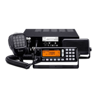
Preamble to the service manual for the IC-F7000 HF TRANSCEIVER.
Essential safety warnings regarding power connection and transceiver handling.
Covers frequency coverage, mode, impedance, stability, power, and physical specs.
Details output power, spurious emissions, carrier suppression, and sideband suppression.
Details receiver sensitivity, squelch sensitivity, and AF output power.
Specifications for the RC-26 remote controller's general features.
Specifications for the SP-25 external speaker's general features.
Identification of key components on the RC-26 circuit boards.
Identification of key components on the HM-146 microphone unit circuit board.
Identification of key components in the IC-F7000 top internal view.
Identification of key components in the IC-F7000 bottom internal view.
Steps to modify the PLL unit for external reference signal input.
Steps to modify the PLL unit for internal reference signal use.
Diagram and instructions for connecting external reference oscillator.
Detailed descriptions of receiver circuits, including RF filters and mixers.
Details on DSP receiver, AGC, and AF amplifier circuits.
Overview of transmitter circuits including microphone amp and speech compressor.
Details on IF amplifier, mixer, and RF circuits including PA and filter units.
Details on ALC, APC, and RF meter circuits.
Detailed description of PLL circuits, including LO and oscillator circuits.
Circuit descriptions for the RC-26 front unit components.
Details of voltage lines for various units (PA, Display, PLL, Main).
Port allocations for Main CPU and output expander ICs.
Port allocations for other expanders, D/A converter, and Front CPU.
Required test equipment and connection setup for adjustments.
Entering, operating, and changing items in adjustment mode.
Specific adjustment procedures for the PLL unit.
Specific adjustment procedures for PA and filter units.
Procedures for noise null point, receiver gain, total gain, S-meter.
Procedures for transmit peak, total gain, TX power, and SWR detector.
List of components for the IC-F7000, including main unit and other parts.
Mechanical parts and disassembly for the RC-26 front and mic units.
Mechanical parts and disassembly for IC-F7000 chassis parts.
Visual identification of transistor, FET, and diode symbols.
Top view board layout for the HM-146 microphone unit.
Top view board layouts for RC-26 connect, rear, and display boards.
Top view board layout for the RC-26 connect board.
Top view board layout for the RC-26 rear board.
Top view board layout for the RC-26 display board.
Board layouts for the IC-F7000 units.
Top view board layout for the IC-F7000 DSP board.
Top view board layout for the IC-F7000 PA unit.
Top view board layout for the IC-F7000 PLL unit.
Top view board layout for the IC-F7000 driver board.
Board layout for the IC-F7000 Varistor-1 board.
Voltage diagrams for RC-26 and HM-146 components.
Voltage diagrams for IC-F7000 units (Main, PA, PLL, DSP).
Voltage diagrams for Main Unit parts (1, 2, 3).
Voltage diagram for the PA unit.
Voltage diagrams for PLL Unit parts (1, 2).
Voltage diagram for the DSP board.
| Modes | FM |
|---|---|
| Weight | 1.2 kg |
| Frequency Range | 136-174 MHz (VHF) |
| Sensitivity | 0.25 μV (at 12 dB SINAD) |
| Number of Channels | 128 |
| Channel Spacing | 25/12.5 kHz |
| Operating Voltage | 13.8 V DC |
| Modulation | FM |
| Operating Temperature Range | -30°C to +60°C |