SECTION 3 DISASSEMBLY INSTRUCTIONS
3 - 1
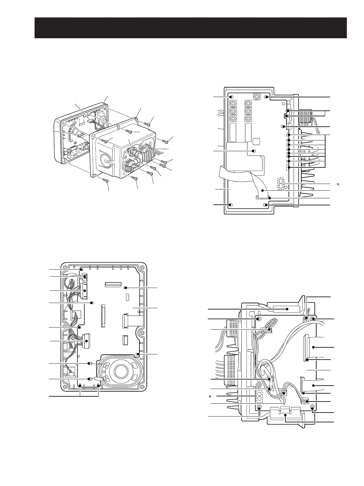
• Opening the transceiver case
1
Unscrew 6 screws A.
2 Disconnect 2 cables from J1 and J5.
3 Remove the front unit.
4 Unscrew 6 screws B, and remove the rear panel.
Front unit
J5
J1
Rear panel
A
A
A
A
A
B
B
B
B
B
B
A
B
J4
J3
LOGIC
board
J6
B
B
B
A
A
B
B
C
C
A
C
J2
MAIN
unit
B
4
B
B
C
C
C
B
D
J6
J9
J8
J11
C
4
D
J12
J1
AF
unit
J2
J5
D
A
A
D
B
• Removing the LOGIC board
1
Disconnect 3 connectors from J6, J4 and J3.
2 Unsolder 2 points A.
3 Unscrew 7 screws B, and remove the LOGIC board from
the front panel.
• Removing the MAIN unit
1
Disconnect the flat cable A from J2.
2 Unsolder 14 points B.
3 Unscrew 6 screws C, and remove the MAIN unit from the
chassis.
• Removing the AF unit
1 Disconnect 2 flat cables A from J1 and J2.
2 Disconnect 6 connectors from J5, J6, J8, J9, J11 and J12.
3 Remove 2 clips B.
4 Unsolder 4 points C.
5 Unscrew 4 screws D, and remove the AF unit from the
chassis.