EasyManua.ls Logo

Icom IC-M504 Service Manual

Icom IC-M504
35 pages
To Next Page IconTo Next Page
Page #1 background imageLoading...
Page #1 background image
SERVICE
MANUAL
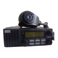
VHF MARINE TRANSCEIVER
S-14225HZ-C1-q
Dec. 2006

Other manuals for Icom IC-M504

Questions and Answers:

Icom IC-M504 Specifications

General IconGeneral
TypeMarine VHF Transceiver
Waterproof RatingIPX7
Power Supply13.8V DC
NMEA ConnectivityNMEA 0183
Frequency Range156.000 - 163.425 MHz
Output Power25 W
ChannelsUSA, INT, CAN channels
ModulationFM
Current Consumption5.5 A

Summary

PRECAUTIONS

SECTION 1 SPECIFICATIONS

GENERAL

General specifications including frequency coverage, impedance, and power requirements.

TRANSMITTER

Detailed specifications for the transmitter section, including output power and modulation.

RECEIVER

Detailed specifications for the receiver section, including sensitivity and selectivity.

SECTION 3 DISASSEMBLY INSTRUCTIONS

Opening the transceiver case

Step-by-step instructions for opening the transceiver case for servicing.

SECTION 4 CIRCUIT DESCRIPTION

4-1 RECEIVER CIRCUITS

Description of the receiver circuits, including antenna switch and RF amplification.

4-2 TRANSMITTER CIRCUITS

Description of transmitter circuits, including microphone amplifier and APC circuit.

4-3 PLL CIRCUITS

Description of Phase Locked Loop (PLL) circuits for frequency stability.

4-4 DSC CIRCUITS

Description of Digital Selective Calling (DSC) circuits for monitoring CH70.

SECTION 5 ADJUSTMENT PROCEDURES

5-1 PREPARATION

Required test equipment and connection diagrams for adjustments.

5-2 FREQUENCY ADJUSTMENT

Procedures for adjusting lock voltage and reference frequency.

5-3 TRANSMIT ADJUSTMENT

Procedures for adjusting transmit output power and deviation.

5-4 RECEIVE ADJUSTMENT

Procedures for adjusting receive sensitivity and squelch.

SECTION 7 MECHANICAL PARTS AND DISASSEMBLY

SECTION 10 BLOCK DIAGRAM

SECTION 11 VOLTAGE DIAGRAM

Related product manuals