4 - 3
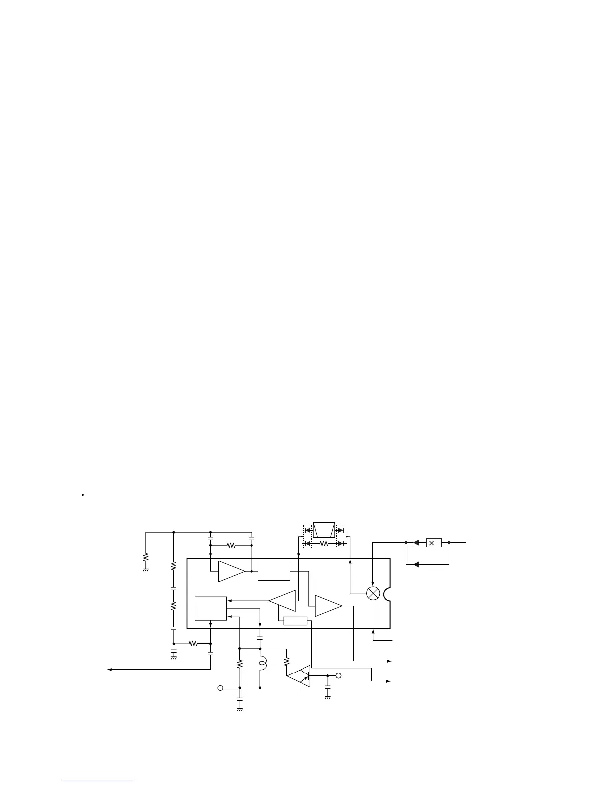
4-1-4 1ST IF AND 2ND MIXER CIRCUITS (RF UNIT)
The 2nd mixer circuit converts the 1st IF signal to a 2nd IF
signal.
The filtered each 1st IF signal from the bandpass filter are
mixed with the 2nd LO signal at the 2nd mixer circuit (IC10,
pin 1) to produce each 2nd IF signal depending on the
receiving frequency.
In AM and FM mode, the 2nd IF signal (26.5 MHz) passes
through the band switching diode (D71) and bandpass filter
(FI3). The filtered signals are then amplified at the 2nd IF
amplifier (Q41), and are applied to the demodulator circuit.
In WFM mode, the 2nd IF signal (13.25 MHz) passes
through the band switching diode (D72) and bandpass filter
(FI4). The filtered signal is then amplified at the 2nd IF
amplifier (Q41), and is applied to the demodulator circuit.
In TV mode, the 2nd IF signal (58.75 MHz) passes through
the band switching diode (D901) and is then applied to the
2nd IF amplifier (Q857). The amplified signal passes
through the bandpass filter (FI901), and is applied to the
demodulator circuit.
4-1-5 DEMODULATOR CIRCUITS (RF UNIT)
The demodulator circuit converts the 2nd IF signal into AF
signals or video signals.
(1) AM, FM AND WFM MODE
The each 2nd IF signals from the 2nd IF amplifier (Q41) are
applied to the 3rd mixer section of the FM IF IC (IC2, pin 16)
and are then mixed with the 3rd LO signal for conversion
into a 450 kHz 3rd IF signal.
IC2 contains the 3rd mixer, limiter amplifier, quadrature
detector and S-meter detector, etc. A frequency from the
PLL reference oscillator (VCO unit; IC3) is used for the 3rd
LO signal (12.80 MHz).
• AM MODE
The 3rd IF signal is output from FM IF IC (IC2, pin 3) and
passes through the ceramic bandpass filter (FI2). The fil-
tered signal is applied to the AM detector circuit (Q44, Q45)
to convert into AF signals, and the signals are applied to the
AF circuit (LOGIC unit).
• FM MODE
The 3rd IF signal is output from FM IF IC (IC2, pin 3) and
passes through the ceramic bandpass filter (FI2). The fil-
tered signal is fed back and amplified at the limiter amplifier
section (pin 5), then demodulated AF signals at the quadra-
ture detector section (pins 10, 11) with detector coil (L21).
The demodulated AF signals are output from pin 9 and are
applied to the AF circuit (LOGIC unit).
• WFM MODE
The 3rd IF signal from the 3rd mixer bypasses the ceramic
filter (FI2) and fed back to the limiter amplifier section (pin 5).
The amplified signal is demodulated at the quadrature
detector section (pins 10, 11) with detector coil (L21). The
AF signals are output from pin 9 and are applied to the AF
circuit (LOGIC unit).
By connecting R55 to R54 in parallel, the output character-
istics of pin 12, “RSSI”, change gradually. Therefore, the FM
IF IC can detect WFM components.

 Loading...


