4 - 5
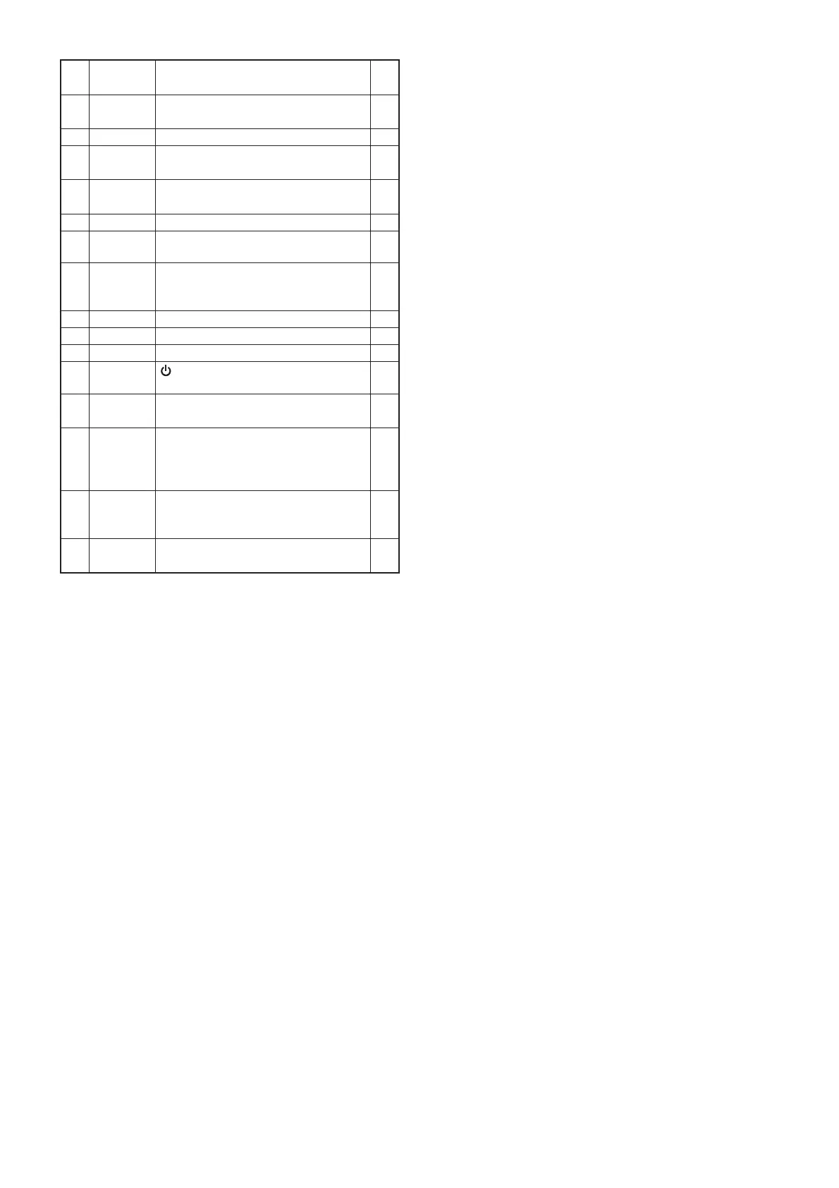
4-5 CPU PORT ALLOCATION (continued)
Pin
No.
Line
Name
Description I/O
114 FUNC
[FUNC] input.
L= Pushed.
I
115 VR_STB Electric volume IC strobe. O
116 IFCON
IF demodulator IC chip enable.
L=Activated.
O
117 CKOUT
CPU clock output. (For tuning voltage
generation)
O
118 BEEP Beep sounds. (Square waves) O
119 NOISE
Noise level detection.
L=Squelch close.
I
120 HVDET
The voltage from the external power
supply or attached battery pack.
L=Power source detection.
I
121 PDAUL PLL IC serial data. O
122 PSTB
PLL
IC strobe. O
123 PCK PLL IC serial clock. O
124 POWER
[
] input.
L=Pushed.
I
125 PPS
PLL IC power save mode control.
L=While in the power save mode.
O
126 DBL2
Doubler circuit (DBL1; Q31, D44,
D47) control.
L= While receiving 494.2–833 MHz
and 1066.7–1309.995 MHz.
O
127 PCON
Main power swtich (LOGIC UNIT:
Q103) control.
L=IC-R6 is power ON.
O
128 +3SC
+3S line control.
L=Receiving.
O
 Loading...


