10
CONNECTING AND MAINTENANCE5
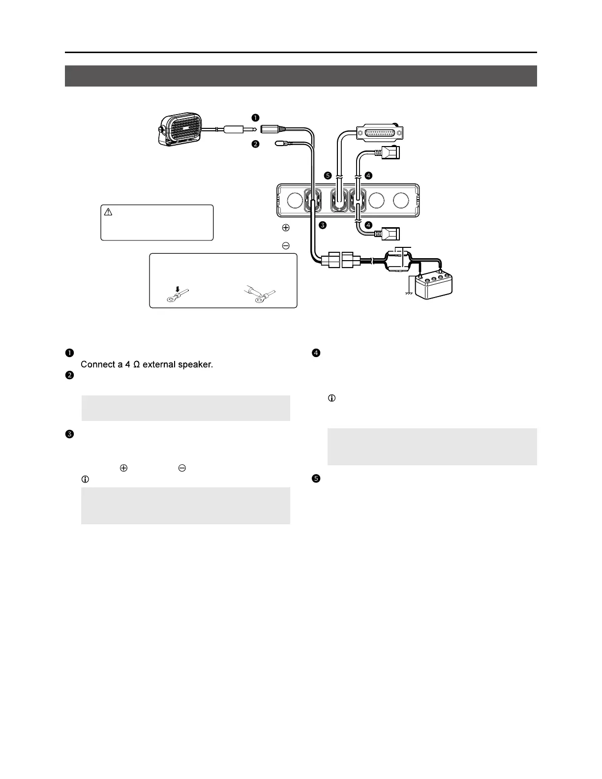
Rear panel connection
EXTERNAL SPEAKER JACK
IGNITION LEAD
Connect to an ignition line.
CAUTION: DO NOT put pressure on this lead.
Binding to the DC power cable is recommended.
DC POWER CONNECTOR
Connect to a 12 V/24 V DC battery.
Pay attention to polarities.
Red line: , Black line:
You can also connect the optional AC adapter.
CAUTION: DO NOT reverse the DC power cable
polarity when connecting to a power source. This
could damage the transceiver.
LAN CABLE
(Gray: for antenna, Black: for IP Network)
Connect the supplied antenna or network devices
such as a HUB.
External power supply output (Gray LAN Cable)
PoE output voltage: 54V
PoE output current: 0.6A
CAUTION: DO NOT connect other than network
devices, such as microphone. This could damage
the transceiver.
D-Sub 25-pin
Connect to use the function extension.
Ask your dealer for details.
Optional
speaker
WARNING! NEVER
remove the fuse holders
from the DC power cable.
Red: ,
Black:
Fuse holders
12 V or 24 V Battery
NOTE: Use the terminals as shown
below for the cable connections.
Crimp Solder