5 - 8
OUTPUT
POWER
(50 MHz)
(144 MHz)
(440 MHz)
(1200 MHz)
ADJUSTMENT ADJUSTMENT CONDITION
MEASUREMENT
VALUE
ADJUSTMENT
UNIT LOCATION
1
2
3
4
5
6
7
8
• Displayed frequency :
51.000 MHz [EUR], [UK], [ITA]
52.000 MHz
[AUS], [SEA], [USA-1]
• Output power : High
• transmitting
• Output power : Low
• Transmitting
• Displayed frequency :
145.000 MHz [EUR], [UK]
147.000 MHz
[ITA], [AUS], [SEA], [USA-1]
• Output power : High
• Transmitting
• Output power : Low
• Transmitting
• Displayed frequency :
445.000 MHz [USA-1]
435.000 MHz [Other]
• Output power : High
• Transmitting
• Output power : Low
• Transmitting
• Displayed frequency :
1270.000 MHz
• Output power : High
• Transmitting
• Output power : Low
• Transmitting
Top
panel
Top
panel
Top
panel
Top
panel
Connect an RF
power meter to the
antenna connector.
Connect an RF
power meter to the
antenna connector.
Connect an RF
power meter to the
antenna connector.
Connect an RF
power meter to the
antenna connector.
more than 5 W
0.5 W
more than 5 W
0.5 W
more than 5 W
0.5 W
more than 5 W
0.5 W
[DIAL]
[DIAL]
[DIAL]
[DIAL]
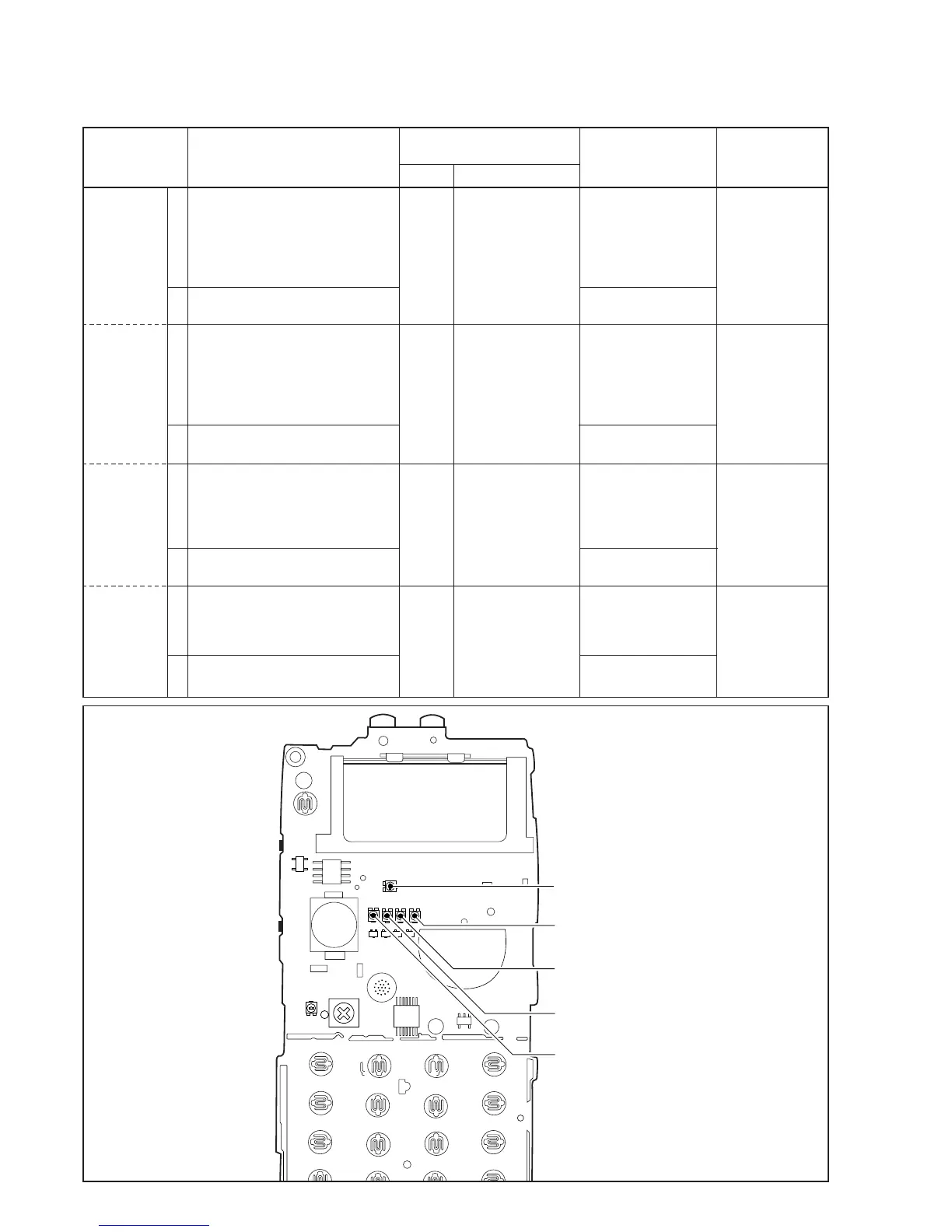
5-4 TRANSMITTER ADJUSTMENT
The following adjustment must be performed at “ADJUSTMENT MODE”.
• LOGIC UNIT TOP VIEW
50 MHz BAND FM deviation adjustment
R327
144 MHz BAND FM deviation adjustment
R325
440 MHz FM deviation adjustment
R326
1200 MHz FM deviation adjustment
R338
DTMF or TONE CALL deviation adjustment
R322