SECTION 3 DISASSEMBLY INSTRUCTIONS
3 - 1
*
)
)
)
*
+
,
LOGIC-1 unit
+
/
.
.
-
,
•
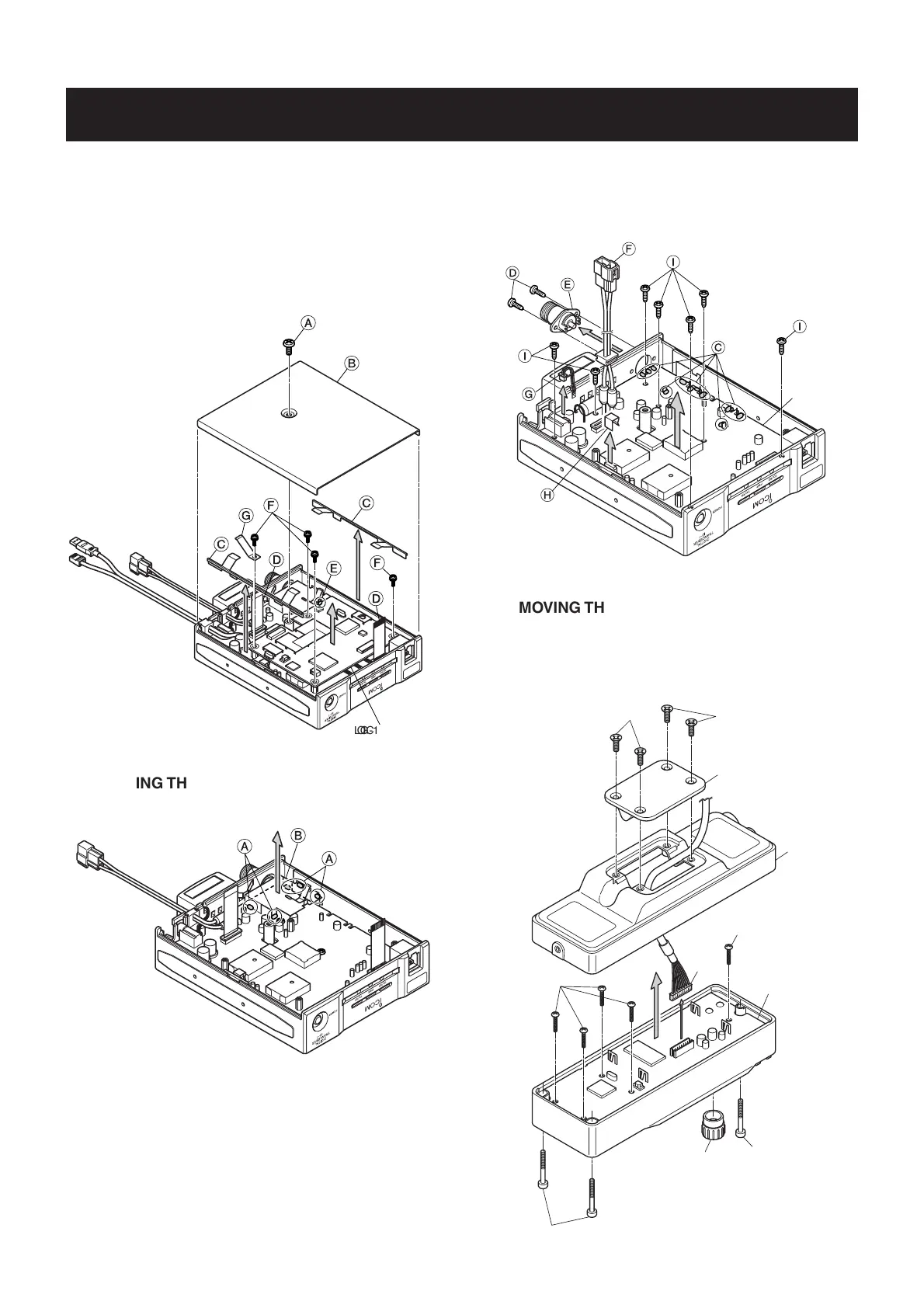
REMOVING THE MAIN UNIT
1 Unsolder 5 points A, and remove the ANT plate B.
3-1 ID-1
•
REMOVING THE LOGIC-1 UNIT
1 Unscrew 1 screw A, and remove the cover B.
2 Remove 2 main shield plates C.
3 Disconnect 2 cables D, and unsolder 1 point E.
4 Unscrew 4 screws F, and remove the earth spring G.
5 Take off the LOGIC-1 unit.
2 Unsolder 11 points C.
3 Unscrew 2 screws D, and remove the ANT connector E.
4 Take off the cable F from the chassis.
5 Disconnect the cable G, and remove the TR-A clip H.
6 Unscrew 7 screws I, and take off the MAIN unit.
MAIN unit
1
+
.
-
/
0
1
,
1
3-2 RC-24
•
REMOVING THE FRONT UNIT
1 Unscrew 4 screws A, and remove the rear plate B.
2 Unscrew 3 screws C, and remove the front panel D.
3 Disconnect the cable E, and remove the knob F.
4 Unscrew 5 screws G, and take off the FRONT unit.
D
E
G
C
F
C
FRONT unit
G
B
A
A
Continue to right above.

 Loading...


