4 - 3
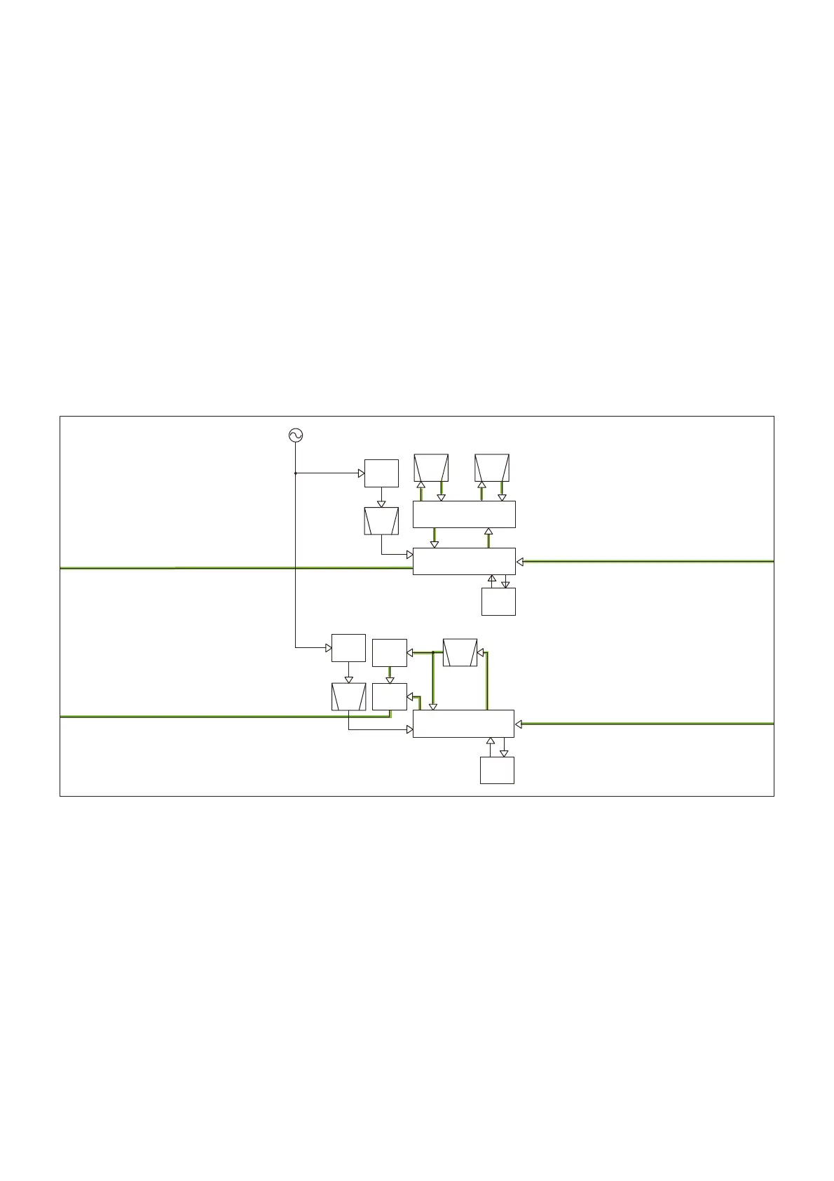
2ND IF CIRCUITS
• Band A
The 1st IF signal from the 1st IF circuit is applied to the IF IC
(IC13, pin 16), which contains the 2nd IF AMP, 2nd mixer, FM
demodulator, and so on.
The 1st IF signal is mixed with the 45.9 MHz 2nd LO signal,
resulting in the 450 kHz 2nd IF signal. The converted sig-
nal is passed through the external 2nd IF fi lter (FM mode;
FI2, FM-N or DV mode; FI1) to remove sideband noise. The
fi ltered signal is amplifi ed by the 2nd IF AMP, and then de-
modulated by the quadrature detector (X2).
The demodulated signal is applied to the RX AF circuit (For
FM and FM-N modes) or digital demodulation circuit (For DV
mode).
Q38
X1
15.3MHz
X3
REF
45.9MHz
-Band A:46.35MHz-
-Band B:61.65MHz-
SW
FM
DISCRI
FM-N/DV
D16,D18,D19
IC13
FI2
W/N
FI1
X2
Q36,D15
FI900
DISCRI
X900
FM
IC901
Q900
61.2MHz
REF
X4
IC18
MODE
SW
Q904
From the 1st IF circuit (Band A).
To the RX AF circuit (Band A).
To the RX AF circuit (Band B).
From the 1st IF circuit (Band A).
BPF
BPF
CERAMIC
BPF
CERAMIC
BPF
CERAMIC
BPF
AM
DET
DET
FM
DET
FM
• Band B
The 1st IF signal from the 1st IF circuit is applied to the IF IC
(IC901, pin 16), which contains the 2nd IF AMP, 2nd mixer,
FM demodulator, and so on.
The 1st IF signal is mixed with the 61.2 MHz 2nd LO signal,
resulting in the 450 kHz 2nd IF signal. The converted signal
is passed through the external 2nd IF fi lter (FI900) to remove
sideband noise.
While receiving in the FM mode, the fi ltered signal is amplifi ed
by the 2nd IF AMP, and then demodulated by the quadrature
detector (X900). The demodulated signal is applied to the RX
AF circuit, through the AF SW (IC18, pins 6, 1).
While receiving in the AM mode, the fi ltered signal is demod-
ulated by Q904 and amplifi ed by the AGC AMP (Q903). The
demodulated signal is applied to the RX AF circuit, through
the AF SW (IC18, pins 7, 1).
• 2ND IF CIRCUITS