4 - 4
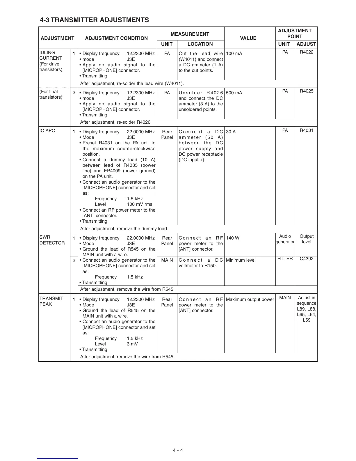
4-3 TRANSMITTER ADJUSTMENTS
IDLING
CURRENT
(For drive
transistors)
(For final
transistors)
IC APC
SWR
DETECTOR
TRANSMIT
PEAK
ADJUSTMENT
ADJUSTMENT ADJUSTMENT CONDITION
MEASUREMENT
VALUE
POINT
UNIT LOCATION UNIT ADJUST
1
2
1
1
2
1
• Display frequency : 12.2300 MHz
• mode : J3E
• Apply no audio signal to the
[MICROPHONE] connector.
• Transmitting
• Display frequency : 12.2300 MHz
• mode : J3E
• Apply no audio signal to the
[MICROPHONE] connector.
• Transmitting
• Display frequency : 22.0000 MHz
• Mode : J3E
• Preset R4031 on the PA unit to
the maximum counterclockwise
position.
• Connect a dummy load (10 A)
between lead of R4035 (power
line) and EP4009 (power ground)
on the PA unit.
• Connect an audio generator to the
[MICROPHONE] connector and set
as:
Frequency : 1.5 kHz
Level : 100 mV rms
• Connect an RF power meter to the
[ANT] connector.
• Transmitting
• Display frequency : 22.0000 MHz
• Mode : J3E
• Ground the lead of R545 on the
MAIN unit with a wire.
• Connect an audio generator to the
[MICROPHONE] connector and set
as:
Frequency : 1.5 kHz
• Transmitting
• Display frequency : 12.2300 MHz
• Mode : J3E
• Ground the lead of R545 on the
MAIN unit with a wire.
• Connect an audio generator to the
[MICROPHONE] connector and set
as:
Frequency : 1.5 kHz
Level : 3 mV
• Transmitting
PA
PA
Rear
Panel
Rear
Panel
MAIN
Rear
Panel
Cut the lead wire
(W4011) and connect
a DC ammeter (1 A)
to the cut points.
Unsolder R4026
and connect the DC
ammeter (3 A) to the
unsoldered points.
Connect a DC
ammeter (50 A)
between the DC
power supply and
DC power receptacle
(DC input +).
Connect an RF
power meter to the
[ANT] connector.
Connect a DC
voltmeter to R150.
Connect an RF
power meter to the
[ANT] connector.
100 mA
500 mA
30 A
140 W
Minimum level
Maximum output power
PA
PA
PA
Audio
generator
FILTER
MAIN
R4022
R4025
R4031
Output
level
C4392
Adjust in
sequence
L89, L88,
L65, L64,
L59
After adjustment, re-solder the lead wire (W4011).
After adjustment, re-solder R4026.
After adjustment, remove the dummy load.
After adjustment, remove the wire from R545.
After adjustment, remove the wire from R545.
 Loading...

