440 01 2021 01
22
AIR FLOW
OFF
ON
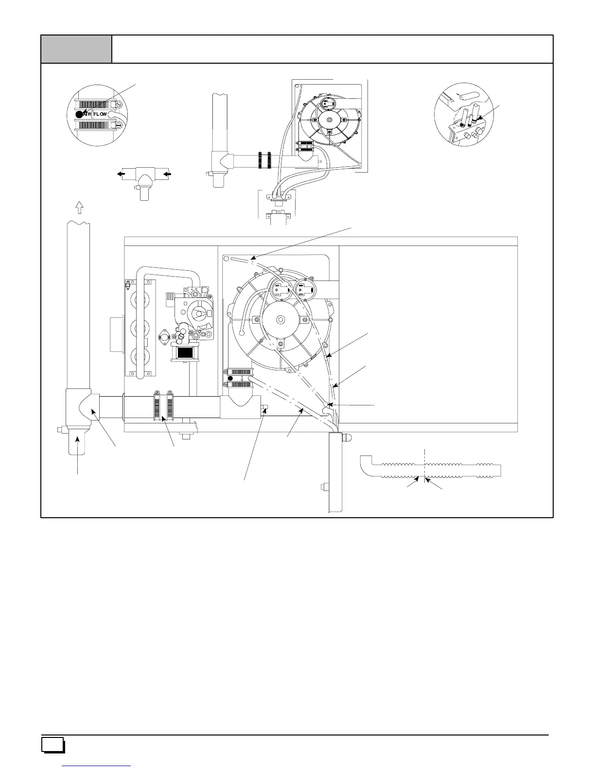
Figure 14
Horizontal Left Thru Top
Plastic Caps
Yellow or black
Vent Drain
&Clamps
Trap Connection
“Clamp ears”
PointedOUT
Preassemble&
insertinto furnace
25--24--70
Single Pressure Switch Detail
Dual Pressure Switch
Tee Trap White PVC
(loose parts bag)
Cap and Clamp
Open End
Flexible tubing connector
3
/
16
²
²²
² OD (Loose Parts Bag)
EXHAUST
Alternate Orienation
Field
SuppliedTee
Cut Here
Cut at straight section
Leave room forclamp
ReliefTube Extension
Black Rubber
3
/
16
²
²²
² ID
Cut to Fit (Loose PartsBag)
AIR FLOW
Coupling & Clamps
(Optional)
Relief Tube
Black Rubber
3
/
16
²
²²
² ID
Drain Tube
Black Rubber
1
/
2
²
²²
² ID&Clamps
Drain Tube Corrugated
5
/
8
²
²²
² ID&Clamps
Horizontal Left--Thru Top (See Figure 14)
Disconnect the hoses from the Trap assembly, and remove Trap
and Trap mounting bracket from the blower compartment. Using
cover plate and gasket provided in the loose parts bag, cover the
hole from the burner compartment to the blower compartment and
secure with screws.
Mount the Trap externally to the bottom side of the unit using the
2 screws provided in the location s hown.
Cut the corrugated tube as shown in the illustration above. Con-
nect the corrugated hose from the transition to the Trap. Secure
connections with clamps.
Remove the black
1
/
2
² ID Drain Tube from the Drain Tee. Install
a yellow cap and clamp over the open drain port of the Drain Tee.
Connect the black
1
/
2
² ID Drain Tube from the Vent Drain to the
Trap. Secure connections with clamps.
Connect the
3
/
16
² ID relief tube to the middle port on the Trap. If an
extension is required, use the
3
/
16
² OD flexible tubing connector
and the black
3
/
16
² ID relief tube in the loose parts bag. Cut tube
to length. Secure all connections with clamps.
Cut an appropriate length of 2² PVC pipe, long enough to exit the
cabinet and connect the vent drain to either:
· A2² PVC coupling fastened onto the Drain Tee
Install Tee Trap into bottom section of Tee and glue pipe.
Connect the Tee trap and the main drain line exiting the casing as
shown in Figure 18.
Note: It is recommended that all PVC piping and fitting connec-
tions be fit up and inspected before final cementing. Both the ex-
ternal Trap and the external Tee Trap must be primed before
operation. Verify all condensate drain connections are securely
clamped. A c oupling and clamps (in loose part bag) may be
installed as shown for future servicing of the vent system.



 To Next Page