37
440 01 2021 01
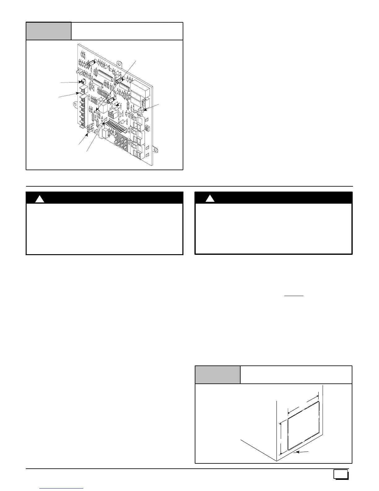
Control Connections
Figure 39
Dip Switch
See “Wiring
Diagram”
for switch settings
FUSE
25--24--74
HUM
DEHUM
Diagnostic Light
24 VAC
HUM
8. Ductwork and Filter
CARBON MONOXIDE POISONING HAZARD.
Failure to properly seal duct could result in death
or personal injury.
Do NOT draw return air from inside a closet or
utility room. Return air duct MUST be sealed to
furnace casing.
!
WARNING
Installation
NOTE:Design and install the air distribution system to comply with
Air Conditioning Contractors of America manuals and/or NFPA
pamphlets 90A and 90B or other approved methods that conform
to local codes and good trade practices.
1. When furnace supply ducts carry air outside furnace area,
seal return air duct to furnace casing and terminate duct out-
side furnace space.
2. Install air conditioning cooling coil (evaporator) on outlet
side of furnace.
3. For furnaces installed without a cooling coil, it is recom-
mended that the outlet duct be provided with a removable
access panel. This panel should be accessible when the
furnace is installed so the exterior of the heat exchanger can
be viewed for inspections. The access panel MUST be
sealed to prevent leaks.
4. If separate evaporator and blower units are used, install
good sealing dampers for air flow control. Chilled air going
through the furnace could cause condensation and shorten
the furnace life.
NOTE:Dampers (field supplied) can be either automatic or manu-
al. Manually operated dampers MUST be equipped with a means
to prevent furnace or air conditioning operation unless damper is in
the full heat or cool position.
CARBON MONOXIDE POISONING HAZARD.
Failure to follow this warning could result in death
or personal injury.
Cool air passing over heat exchanger can cause
condensate to form resulting in heat exchanger
failure.
!
WARNING
Connections
NOTE: On upflow installations, return air can enter through either
side, both sides, or the bottom. On horizontal or downflow installa-
tions the return air must enter through the knockout opening in the
lower panel of the furnace. Return air cannot
enter through rear of
the furnace. When the furnace is located in an area near or adja-
cent to the living area, the system should be carefully designed
with returns to minimize noise transmission through the return
grille. Any blower moving a high v olume of air will produce audible
noise which could be objectionable to when the unit is located very
close to living areas. It is advisable to route the return air ducts un-
der the floor or through the attic.
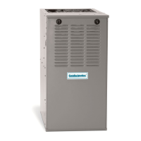
1. For side c onnections using a 16² x25² filter, cut out the em-
bossedareashowninFigure 4 0 . This will provide a 14
1
/
2
² x
22
1
/
2
² approximate opening.
Figure 40
Side Return Air Cutout
Embossed Area
on Side of Furnace
A=14
1
/
2
² Height of Cutout for 16² x25² Filter
B=22
1
/
2
² Width of Cutout for 16² x25² Filter
A
Furnace
Bottom
B