440 01 2021 01
38
NOTE:Furnaceswith5 TONSc ooling rating REQUIRE two(2)
side returns or one side return with bottom return.
2. Bottom returns can be made by removing the knockout pan-
el in the furnace base. Do NOTremove knock-out except for
a bottom return.
3. Installation of locking -type dampers are recommendedin all
branches, or in individual ducts to balance system’s air flow.
4. Non-combustible, flexible duct connectors are recom-
mended for return and supply connections to furnace.
5. If air return grille is located close to the fan inlet, install at
least one, 90 ° air turn between fan and inlet grille to reduce
noise.
NOTE:To further reduce noise, install acoustical air turning vanes
and/or line the inside of duct with acoustical material.
Sizing
Existing or new ductwork MUST be sized to handle the correct
amount of airflow for either heating only o r heating and air condi-
tioning.
Insulation
1. Insulate ductwork installed in attics or other areas exposed
to outside temperatures with a minimum of 2² insulation and
vapor barrier.
2. Insulate ductwork in indoor unconditioned areas with a mini-
mum of 1² insulation with indoor type vapor barrier.
Filters
A Filter must be used:
Filters are not supplied with these furnaces, but can be purchased
from dealer.
Use either filter type:
· Washable, high velocity filters are based on a maximum
air flow rating of 600 FPM.
· Disposable, low velocity filters are based on a maximum
air flow of 300 FPM when used with filter grille.
NOTE:Disposable, low velocity filters may be replaced with wash-
able, high velocity filter providing they meet the minimum size
areas. Washable, high velocity filters can be replaced ONLY with
same type and size.
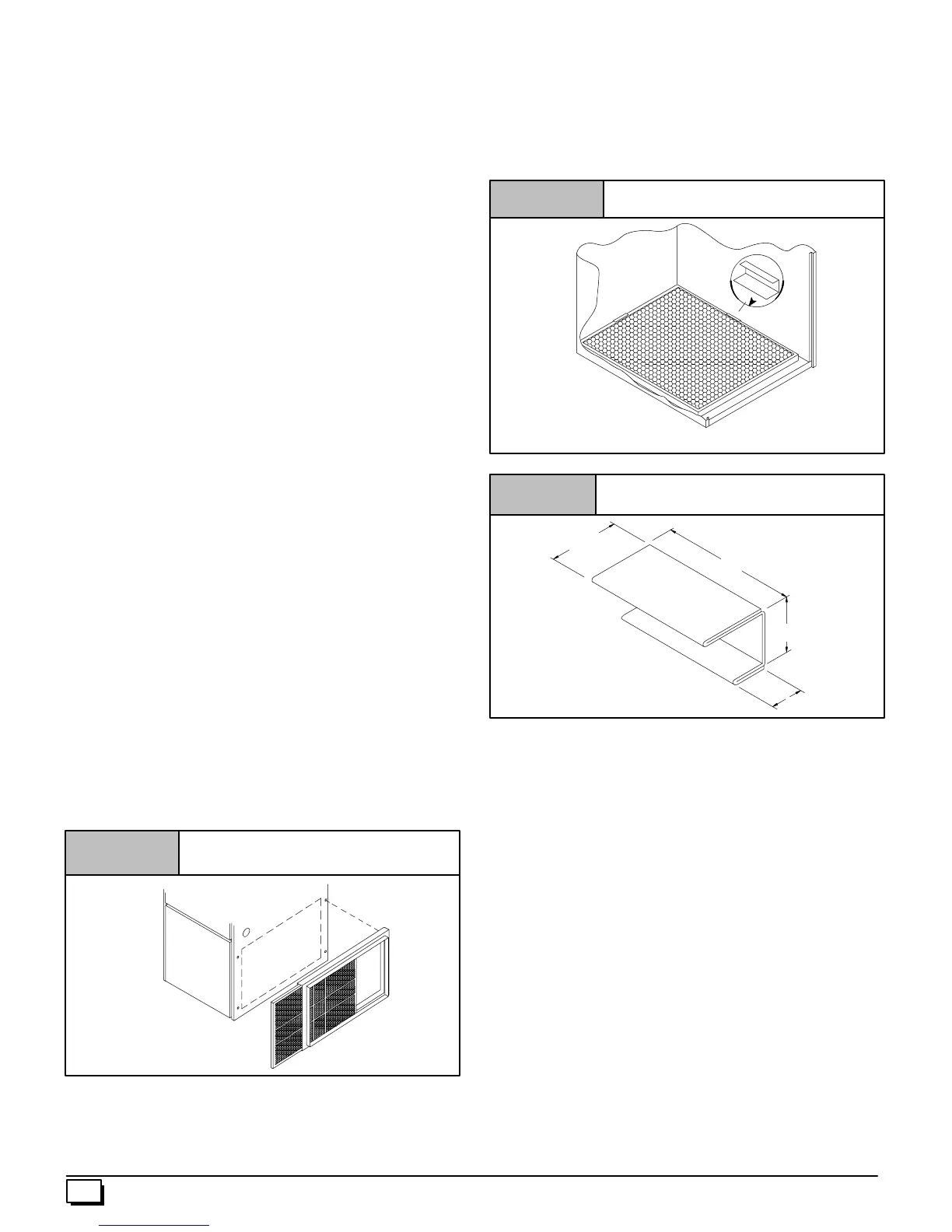
Figure 41
Side Mounted Filter Rack
25--20--90
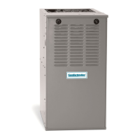
Filter Installation using Filter Rack
When installing or removing a bottom mounted filter, slide the two
side filter clips to the back of the furnace BEFORE installing or re-
moving. This will allow the filter to clear the front raised edge of the
furnace. Insert filter into side clips first and push filter back until it is
fully engaged into back clip. When filter is in place, slide clips back
into place midway on filter as shown in Figure 42 or Figure 43.
Figure 42 Bottom Mounted Filter Rack
Slide filter clips towards back before removing
25--24--18
Figure 43 Filter Clip Construction
3²
1
1
/
4
²
1
1
/
2
²
11
/
16
²
26 Ga. Galvanized Steel
Refer to Figure 44 and for guidelines to install filters. Furnaces
which require larger filter media and have limited clearances on
one side of furnace, require a standoff filter rack, see Figure 4 4 ,
available from your distributor.
CAUTION
If filters are only suitable for heating application, advise
homeowner that filter size may need to be increased if air
conditioning is added.
Addition Of Air Conditioning
When a refrigeration coil is used in conjunction with this unit, it
must be installed parallel with or on the discharge side of the unit to
avoid condensation on the heat exchanger. The coil installation in-
structions must be consulted for proper coil location and installa-
tion procedures. With a parallel flow arrangement, dampers must
be installed to prevent chilled air from entering the furnace. If
manually operated dampers are used, they must be equipped with
a means to prevent operation of either unit unless the damper is in
full heat or full cool position.
A3² clearance is required on the right side of the furnace in order to
run the condensate drain line. Copper, iron or plastic tubing may be
used for the condensate drain line.
 Loading...