27
440 01 2021 01
Joining Pipe and Fittings
CARBON MONOXIDE POISONING HAZARD
Failuretofollowthiswarningcouldresultindeathor
personal injury.
Do NOT use solvent cement that has become
curdled, lumpy or thickened and do NOT thin.
Observe precautions printed on containers. For
applications below 32° F., use only low temperature
type solvent cement. Poor joints may lead to
disconnected or leaking vent pipe joints allowing
carbon monoxide t o enter the living space.
!
WARNING
1. Cut pipe end square, remove ragged edges and burrs.
Chamfer end of pipe, then clean fitting, socket and pipe joint
of all dirt, grease, or moisture.
NOTE:Stir the solvent cement frequently while using. Use a natu-
ral bristle brush or the dauber supplied with the cement. The prop-
er brush size is one inch.
2. After checking pipe and socket for proper fit, wipe socket
and pipe with cleaner-primer. Apply a liberal coat of primer
to inside surface of socket and outside of pipe. Do NOT al-
low primer to dry before applying cement.
3. Apply a thin coat of cement evenly in the socket. Quickly ap -
ply a heavy c oat of cement to the pipe end and insert pipe
into fittings with a slight twisting movement until it bottoms
out.
NOTE: Cement MUST be fluid while inserting pipe. If NOT, recoat
pipe.
4. Hold the pipe in the fitting for 30 seconds to prevent the ta-
pered socket from pushing the pipe out of the fitting.
5. Wipe all excess cement from the joint with a rag. Allow 15
minutes before handling. Cure time varies according to fit,
temperature and humidity.
Connecting Vent Pipes and Termination
NOTE: Combustion air intake and vent MUST terminate in the
same atmospheric pressure zone. If installation is in a cold climate
(sustained temperatures below 0° F), increase the minimum dis-
tance between vent pipe and air intake from 8² to 18².
CARBON MONOXIDE POISONING HAZARD.
Failure to properly vent this furnace could result
in death or personal injury.
Maintain a minimum of 36² between combustion
air inlet and clothes dryer vent. Terminate the
combustion air intake as far as possible from any
air conditioner, heat pump, swimming pool,
swimming pool pumping, chlorinator or filtration
unit.
!
WARNING
1. Install all couplings, nipples and elbows using proper proce-
dures for Joining Pipe and Fittings and maintain spacing
between vent and combustion air piping as indicated in
Figure 20 through Figure 27.
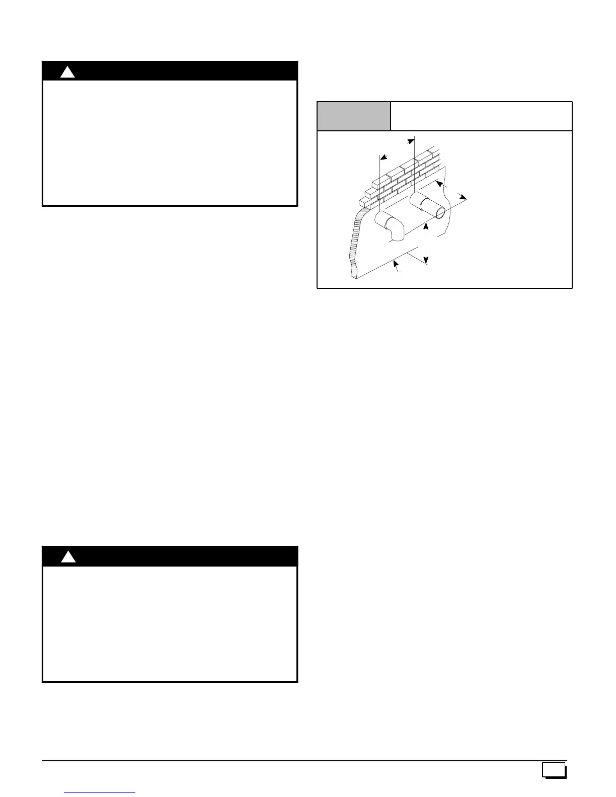
Figure 20
Sidewall Termination 12² or More
Above Snow Level or Grade Level
8” *
MIN.
20’
MAX
8”
MIN.
*18²
²²
² Minimum for cold climates
(substainedbelow 0°
°°
° F)
25--00--05F
GRADE LEVEL
OR
SNOW LEVEL
12 ”
MIN.
Horizontal Termination
1. Cut two holes. 2
1
/
2
² for 2² pipe, 3² for 2
1
/
2
² pipe, or 3
1
/
2
² for
3² pipe. Do NOTmake the holes oversized, or it will be nec-
essary to add a sheet metal or plywood plate on the outside
with the c orrect size hole in it.
2. Check hole sizes by making sure it is smaller than the cou-
plings or elbows that will be installed on the outside. The
couplings or elbows MUST prevent the pipe from being
pushed back through the wall.
3. Extend vent pipe and combustion air pipe through the wall
3
/
4
² to 1² and seal area between pipe and wall.
4. Install the couplings, nipple and termination elbows as
shown and maintain spacing between vent and combustion
air piping as indicated in Figure 20 and Figure 21.
A metal shield is recommended 18² x18² min. or 18² min. diameter
around the vent termination at the exterior wall to protect the house
exterior materials from flue product or condensation (freezing)
damage.
Using Exterior Risers
1. Install elbows and pipe to form riser as shown in Figure 21.
2. Secure vent pipe to wall with galvanized strap or other rust
resistant material to restrain pipe from moving.
3. Insulate pipe with Armaflex or equivalent moisture resistant
closed cell foam insulation or Fiberglass insulation if boxed
in and sealed against moisture.
Vertical Termination
1. Figure 22 shows the proper installation and clearances for
vertical vent termination. The vertical roof termination
should be sealed with a plumbing roof boot or equivalent
flashing. The inlet of the intake pipe and end of the exhaust
vent must be terminated no less than 12² above the roof or
snow accumulation level, and 12² away from a vertical wall
or other protrusion.



 To Next Page