BPVC
Vent/Exhaust
B
PVC Intake/Combustion Air
Concentric Vent Dimensional
Drawing
D
A
1
1
/
2
²
²
25--22--03
C
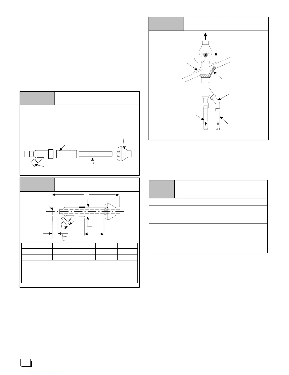
Figure 31
440 01 2021 01
30
Vertical & Horizontal Termination
1. Determine the pipe diameters required for the installation
from Table 5 and Figure 31.
2. Determine the best location for the termination kit. See
Figure 30 for vertical termination or Figure 29 and
Figure 34 for horizontal termination. Roof termination is
preferred since it is less susceptible to damage, has re -
duced intake contaminants and less visible vent vapor. For
side wall termination, consideration should be given to: 1)
possible damage from the vapors to plants/shrubs, other
equipment and building materials, 2) possible damage to
the terminal from foreign objects, 3) wind effects that may
cause recirculation of flue products, debris or light snow and
4) visible vent vapor.
2or2
1
/
2
² Dia.
SDR--26 Pipe
Kit Components
Kit Contents:
3² Rain Cap or 2² Rain Cap
3² Diameter SDR--26 Pipe, 19
1
/
2
² Long or
4² Diameter SDR--26 Pipe, 37
1
/
8
² Long,
2² Diameter SDR--26 Pipe, 31
5
/
8
² Long or
2
1
/
2
² Diameter SDR--26 Pipe, 24² Long,
3² Y Concentric Fitting or 2² Y Concentric Fitting
2² or 3² Dia.
Rain Cap
Nominal 3² or 4² Dia.
SDR--26 Pipe
2² or 3² Dia.
Y Concentric Fitting
25--22--03
Figure 29
Maintain 12² min. clearance
above highest anticipated
snow level. Max. of 24²
above roof.
Combustion
Air
Roof Boot/
Flashing
(Field Supplied)
Combustion
Air
Vent
Concentric Vent Roof Installation
Vent
Support
(Field Supplied)
45° Elbow
(Field Supplied)
25--22--02
Note:
Support must be field installed to secure termination kit to structure.
Figure 30
3. Cut one 5² diameter hole through the structure for the
NAHA001CV Kit or one 4² diameter hole for the
NAHA002CV Kit .
4. Dimension D may be lengthened to 60² max. or shortened
by cutting the pipes to 12² min. Dimension A will change ac-
cording to D dimension. (See Figure 31)
Model A* B C D**
NAHA001CV 33
3
/
8
2 3
1
/
2
16
7
/
8
NAHA002CV 38
7
/
8
3 4
1
/
2
21
1
/
8
* = Dimension will change accordingly as dimension D is
lengthened or shortened.
** = Dimension D may be lengthened to 60² may also be shortened
by cutting the pipes provided in the kit to 12² minimum
Table 5
Concentric Termination Kit
NAHA001CV & NAHA002VC Venting
Table Dual Piping O NLY
75,000 Btuh Furnace
NAHA002CV -- 35¢
¢¢
¢ & (4) 90° elbows with 2² PVC pipe
125,000 Btuh Furnace
NAHA001CV -- 35¢ & (4) 90° elbows with 3² PVC pipe
1. Do not include the field supplied 45° elbow in the total
elbow count.
2. If more than four elbows are required, reduce the length
ofboththeinletandtheexhaustpipesfivefeetforeach
additional elbow used.
3. Elbows are DWV long radius type for 2
² and 3² vents.
If more than four elbows are required, reduce the length of
both the inlet and exhaust pipes 5¢ for each additional elbow
used.
*Feetof pipe is whicheverpipe runis thelongest, eitherinlet
or outlet side.
If assembly needs to be extended to meet height or side wall thick-
ness requirement, the two pipes supplied in the kit may be re-
placed by using the same diameter solid, single (no coupling
connections) field supplied SDR--26 PVC (ASTM D2241) pipes.
Do not extend dimension D more than 60².(SeeFigure 31)
Do not use field supplied couplings to extend the pipes.
Airflowrestrictionwilloccurandthefurnacepressureswitch
may cause intermittent operation.
5. Partially assemble the c oncentric vent termination kit.
Clean and cement the parts using the procedures for Join-



 To Next Page