5
440 01 2021 01
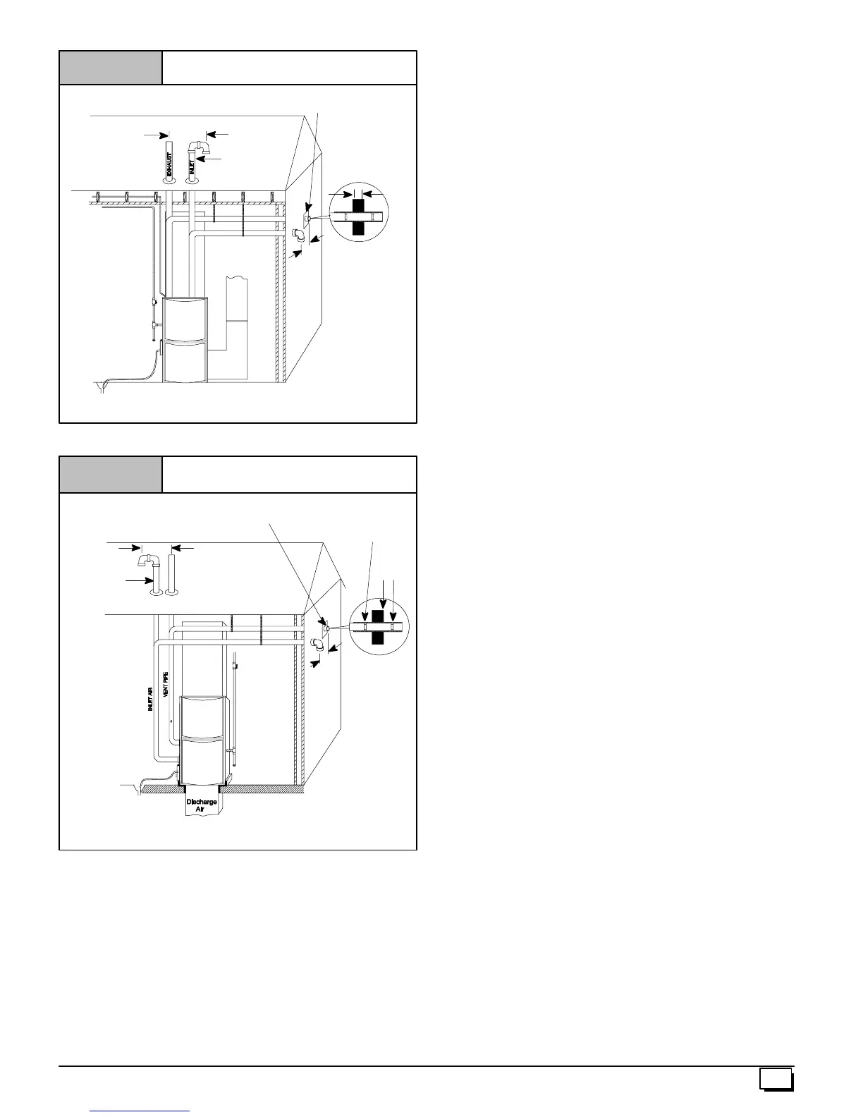
Vent Pipes MUST be
supported
Horizontally and
Vertically
*8² Min.
20¢ Max.
insameatmosphericzone
*8² Min.
20¢ Max.
in same
atmospheric
zone
Couplingon endsof
exhaust pipe. Total
pipe & coupling out-
side structure = 8²
Figure 1
Typical Upflow Installation
Aluminumor non-- rustingshield recommended.
(SeeVent TerminationShielding fordimensions).
*Increaseminimumfrom8²
²²
² to18²
²²
² forcoldclimates(sustainedtemperatures
below 0 °
°°
° F).
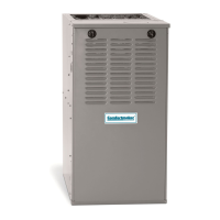
DISCHARGEAIR
25--23--33
InletPipe
(notused on
SinglePipe
model)
*8² Min.
20¢ Max.insame
atmosphericzone
Figure 2 Typical Downflow Installation
Vent Pipes MUST
besupportedHorizon-
tally and Vertically
* Increaseminimumfrom8²
²²
² to18²
²²
² forcoldclimates(sustainedtemperatures
below 0°
°°
°F).
See Vent Termination
Shielding inVentSection.
*8² Min.
20¢ Max.
in same
atmosphericzone
8² Min.
Coupling on inside
andoutsideofwallto
restrainvent pipe
25--23--33a
InletPipe
(notused on
SinglePipe
model)
Installation Requirements
1. Install furnace level.
2. This furnace is NOT to be used for temporary heat of build-
ings or structures under construction.
3. Install furnace as centralized as practical with respect to the
heat distribution system.
4. Install the vent pipes as short as practical, and in accor -
dance to these instructions. (See Vent and Combustion
Air Piping section).
5. Maintain clearance for fire safety and servicing. A front
clearance of 24² is required for access to the burner, con-
trols and filter. See clearance requirements in Figure 4.
6. Use a raised base for upflow furnace if the floor is damp or
wetattimes.
7. For downflow installations, non combustible subbase must
be used under the furnace unless installation is on a non
combustible floor surface. This requirement applies even
when a c oil box or cabinet is used.
8. For horizontal installations, line contact is permissible only
between lines formed by intersection of back and two sides
of furnace jacket, and building joists, studs or framing.
9. Residential garage installations require:
· Burners and ignition sources installed at least 18² above
the floor.
· Located or physically protected from possible damage by
a vehicle.
10. Local codes may require a drain pan under the entire fur-
nace and condensate trap when the furnace is installed in
attic application.
This furnace may be used for construction heat provided that all
the following conditions are met:
· The furnace is permanently installed with all electrical wir-
ing, piping, venting and ducting installed according to these
installation instructions. A return air duct is provided, sealed
to the furnace casing, and terminated outside the s pace
containing the furnace. This prevents a negative pressure
condition as created by the circulating air blower, causing a
flame rollout and/or drawing c ombustion products into the
structure.
· The furnace is controlled by a thermostat. It may not be “hot
wired” to provide heat continuously to the structure without
thermostatic control.
· Clean outside air is provided for combustion. This is to mini-
mize the corrosive effects of adhesives, sealers and other
construction materials. It also prevents the entrainment of
drywall dust into combustion air, which can cause fouling
and plugging of furnace components.
· The temperature of the return air to the furnace is main-
tained between 55° F(13° C) and 80° F(27° C) , with no eve-
ning setback or shutdown. The use of the furnace while the
structure is under construction is deemed to be intermittent
operation per our installation instructions.
· The air temperature rise is within the rated rise range on the
furnace rating plate, and the firing rate has been set to the
rating plate value.
· The filters used to clean the circulating air during the
construction process must be either changed or thoroughly
cleaned prior to occupancy.
· The furnace, ductwork and filters are cleaned as necessary
to remove drywall dust and construction debris from all
HVAC system components after construction is completed.
· After c onstruction is complete, verify furnace operating con-
ditions including ignition, input rate, temperature rise and
venting according to these instructions.