18
441 01 2611 06
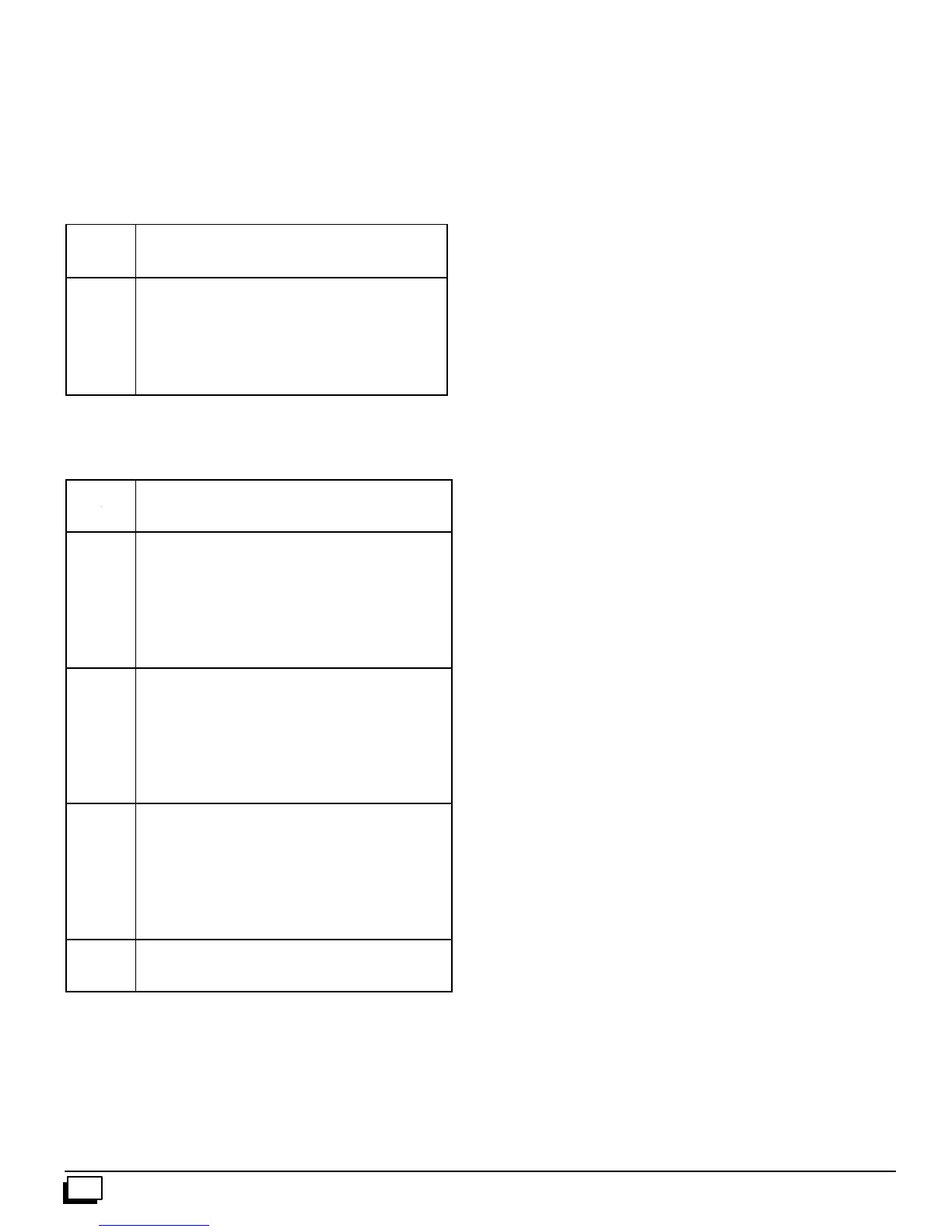
Exterior Masonry Chimney,
FAN+NAT Installations with
Type--B Double--Wall Vent Connectors
ã
ãã
ã NFPA&AGA
Table A--
Combined Appliance
Maximum Input Rating in
Thousands of Btu per Hr
VENT
HEIGHT
INTERNAL AREA OF CHIMNEY
(SQ IN.)
(FT)
12 19 28 38
6 74 119 178 257
8 80 130 193 279
10 84 138 207 299
15 NR 152 233 334
20 NR NR 250 368
30 NR NR NR 404
Table B--
Minimum Allowable Input Rating of
Space--Heating Appliance in
Thousands of Btu per Hr
VENT
HEIGHT
INTERNAL AREA OF CHIMNEY
(SQ IN.)
(FT)
12 19 28 38
Local 99% Winter Design Temperature: 17 to 26°
°°
° F*
6 0 55 99 141
6
°
°
°
°F
8 52 74 111 154
o2
10 NR 90 125 169
7t
15 NR NR 167 212
1
20 NR NR 212 258
30 NR NR NR 362
Local 99% Winter Design Temperature: 5 to 16°
°°
° F*
6 NR 78 121 166
°
°
°
°F
8 NR 94 135 182
16
10 NR 111 149 198
5t
15 NR NR 193 247
20 NR NR NR 293
30 NR NR NR 377
Local 99% Winter Design Temperature: --10 to 4°
°°
° F*
6 NR NR 145 196
4
°
°
°
°F
8 NR NR 159 213
to
10 NR NR 175 231
10
15 NR NR NR 283
--
20 NR NR NR 333
30 NR NR NR NR
-- 11 °
°°
° F
or
Local 99% Winter Design Temperature: --11°
°°
° For
lower*
lower
Not recommended for any vent configuration
* The 99% Winter Design Dry--Bulb (db) temperatures are found in the
1993 ASHRAE Fundamentals Handbook, Chapter 24, Table 1
(United States) and 2 (Canada), or use the 99.6% heating db
temperaturesfound in the 1997 or 2001 ASHRAE Fundamentals
Handbook, Climatic Design Information chapter, Table 1A (United
States) and 2A (Canada).
Inspectionsbeforethesaleandatthetimeofinstallationwilldeter-
minetheacceptabilityofthechimney ortheneedforrepairand/or
(re)lining. Refer to the Chimney Inspection Chart to perform a
chimney inspection.
If the inspection of a previously used tile--lined chimney:
a. Showssignsofventgas condensation,the chimneyshould
be relined in accordance withlocal codes and theauthority
having jurisdiction. The chimney should be relined with a
listed metal liner, Type--B vent, or a listed chimney adapter
kittoreducecondensation. Ifacondensatedrainisrequired
bylocalcode,refertotheNFGC,Section10.9foradditional
information on condensate drains.
b. Indicates the chimney exceeds the maximum permissible
sizeinthetables,thechimneyshouldberebuiltorrelinedto
conform to the requirements of the equipment being
installed and the authority having jurisdiction.
Achimneywithouta c lay tileliner, whichis otherwiseingoodcon-
dition,shallberebuilttoconformtoANSI/NFPA211orbelinedwith
a UL listed (ULClisted in Canada)metalliner or UL listed Type--B
vent. Relining with a listed metal liner or Type--B vent is consid-
ered to be a vent--in--a--chase.
If a metal liner or Type--B vent is used to line a chimney, no other
appliance shall be vented into the annular s pace between the
chimney and the metal liner.
APPLIANCE APPLICATION REQUIREMENTS
Appliance operation has a significant impact on the performance
of the venting system. If the appliances are sized, installed, ad-
justed, and operated properly, the venting system and/or the ap-
pliances should not sufferfrom condensation and corrosion. The
ventingsystemandallappliancesshallbeinstalledinaccordance
with applicable listings, standards, and codes.
The furnace should be sized to provide 100 percentof the design
heating load requirementplus any margin that occurs because of
furnace model size capacity increments. Heating load estimates
can be made using approved methods available from Air Condi-
tioning Contractors of America (Manual J); American Society of
Heating, Refrigerating, and Air--Conditioning Engineers; or other
approved engineering methods. Excessive oversizing of the fur-
nace could cause the furnace and/or vent to fail prematurely.
Whenametalventormetallinerisused,thev entorlinermustbein
goodconditionandbeinstalledinaccordancewiththeventorliner
manufacturer’s instructions.
To prevent condensation in the furnace and vent system, the fol-
lowing precautions must be observed:
1. Thereturn--airtemperaturemustbeatleast60°Fdbexcept
forbriefperiodsoftimeduringwarm--up fromsetback at no
lower than 55°F db or during initial start--up from a standby
condition.
2. Adjust the gas input rate per the installation instructions.
Lowgasinputratecauseslowventgastemperatures,caus-
ing condensation and corrosion in the furnace and/or vent-
ing system. Derating is permitted only for altitudes above
2000¢.
3. Adjust the air temperature rise to the midpoint of the rise
rangeorslightlyabove. Lowairtemperaturerisecancause
low vent gas temperature and potential for condensation
problems.
4. Set the thermostat heat anticipator or cycle rate to reduce
short cycling.
Air for combustion must not be contaminated by halogen com-
poundswhichincludechlorides,fluorides,bromides,andiodides.
These compounds are found in many common home products
suchasdetergent,paint,glue,aerosolspray,bleach,cleaningsol-
vent,salt, and airfreshener, and can cause corrosion of furnaces
and vents. Avoidusing such products in the combustion--air sup -
ply. Furnace use during construction of the building could cause
thefurnacetobeexposedtohalogencompounds,c ausingprema-
ture failure of the furnace or venting system due to corrosion.