23
441 01 2611 06
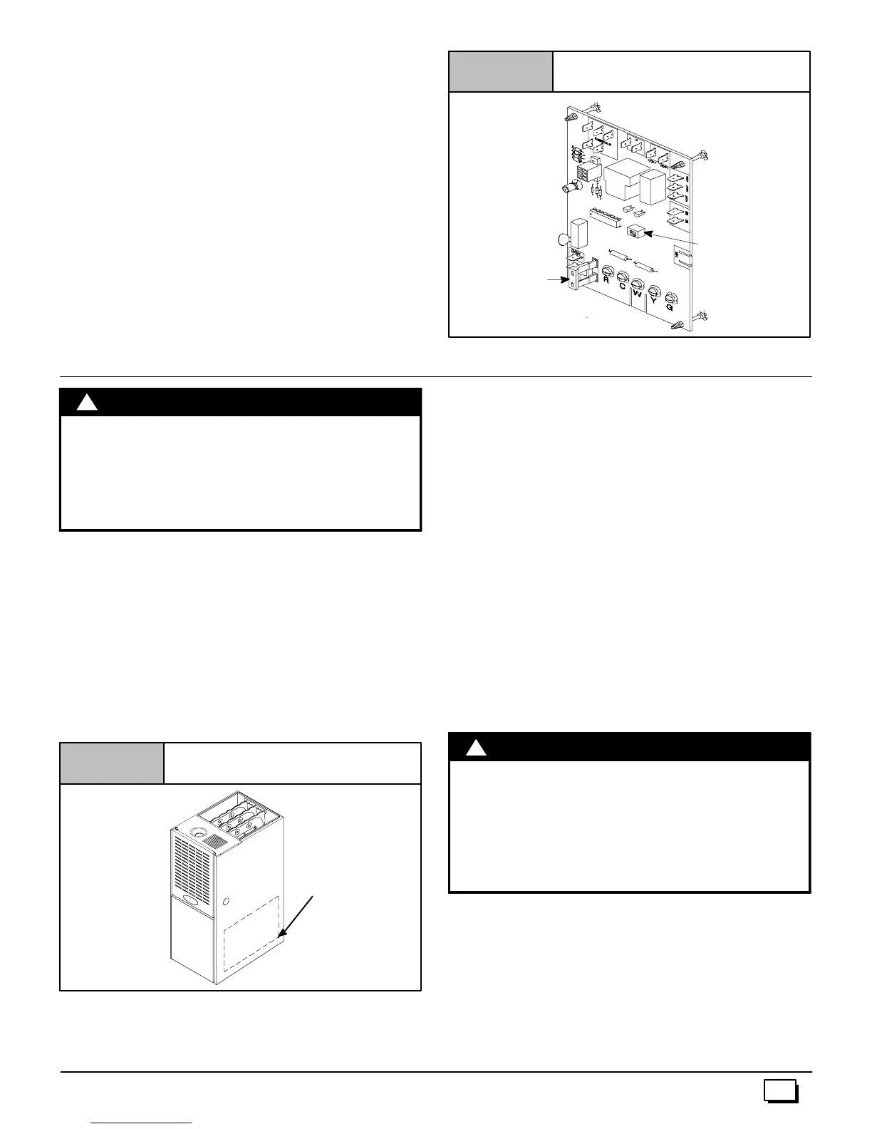
Fan Control
ThefancontrolispresetatthefactorywithONdelayof30seconds
in the heating mode. The blower OFF timing is preset at 140sec-
onds. If desired,the fan OFF delay can bereset to obtain thelon-
gest delay times while still maintaining comfort levels. See
“Furnace Wiring Diagram”.
Control Center Fuse
The 24V circuit contains a 5--amp, automotive--type fuse located
oncontrolcenter.(SeeFigure 20 )Anyelectricalshortsof24Vwir-
ingduring installation,service,ormaintenancemaycausefuseto
blow. If fuse replacement is required, use only a fuse of identical
size (5 amp.).
Fan Timer Connections
Figure 20
DIP Switch
FUSE
25--23--41
10. Ductwork and Filter (Upflow/Horizontal)
CARBON MONOXIDE POISONING HAZARD.
Failure to properly seal duct could result in death
and/or personal injury.
DoNOT draw returnair from inside a closet or utility
room where furnace is located. Return air duct
MUST be sealed to furnace casing.
!
WARNING
Duct Connections
This furnace may be installed in only a bottom or side return--air
duct application. Return air duct connections through the back of
the furnace is NOT permitted.
Upflow ONLY: Side return--air duct connections can be made by
cutting out the embossed area shown in Figure 21. A plugged
holeisprovidedateachfurnacesideductlocationtohelpstartcut-
tingtheopening. Sideductc onnectionsareNOTpermittedinhori-
zontal flow applications.
Cutting Side Return Air Opening
Figure 21
Plugged
Starting
Hole
Upflow and Horizontal Flow: Bottom return--air duct connec-
tions can be made by removing the knockout panel in thefurnace
base. Do NOT remove knock-out except for a bottom return--air
duct connection.
Duct Design
Designandinstallairdistributionsystemto complywithAirCondi-
tioning Contractors of America manuals or other approved meth-
ods that conform to local codes and good trade practices.
Whenthefurnaceislocatedinanareanearoradjacenttotheliving
area,thesystemshouldbecarefullydesignedwithreturnstomini-
mize noise transmission through the return air grille. Any blower
movingahighvolumeofairwillproduceaudiblenoise,whichcould
beobjectionablewhenthefurnaceislocatedvery closetoaliving
area. It is often advisable to route the return air ducts under the
floor or through the attic.
· Refer to furnace Technical Support Manual (Blower Data)
for air flow information.
· Sizeductworktohandleairflowforheating(andaircondition-
ing if so equipped).
Duct Installation Requirements
· When a furnace is installed so that supply ducts carry aircir-
culated by the furnace to areas outside of the space contain-
ingthefurnace,thereturnairshallalsobehandledby duct(s)
sealed to the furnace casing and terminating outside the
space containing the furnace.
CARBON MONOXIDE POISONING HAZARD.
Failure to follow safety warning exactly could
result in serious injury, d eath, and/or property
damage.
Install cooling coil on furnace discharge. Cool air
passing over heat exchanger could cause conden-
sate to form resulting in heat exchanger failure.
!
W
RNING
· Whenthefurnaceisusedwithacoolingunit,thefurnaceshall
beinstalledparallelwithorontheupstreamsideofthecooling
unit to avoid condensation in the heating element.
· Withaparallelflowarrangement,thedampersorothermeans
usedto controlflowofair shallbeadequatetopreventchilled
airfromenteringthefurnace.Chilledairgoingthroughthefur -
nace could cause condensation and shorten furnace life.
Dampers (purchased locally) can be either automatic or
manual. Manuallyorautomatically operateddampersMUST
be equipped with a means to prevent furnace and air condi-
tioningoperation,unlessdamperisinthefullheatorcoolposi-
tion.