19
441 01 2611 06
Vent dampers on any appliance connected to the common vent
cancausecondensationandcorrosion in the ventingsystem. Do
notuseventdampersonappliancescommonventedwiththisfur-
nace.
8. Gas Supply and Piping
CARBON MONOXIDE POISONING, FIRE AND
EXPLOSION HAZARD.
Failure to follow safety warnings exactly could
result in serious injury, death, and/or property
damage.
Models designated for Natural Gas are to be used
withNaturalGasONLY,unlessproperlyconvertedto
use with LP gas.
!
WARNING
Gas Supply Requirements
· UseonlytheTypeofgasapprovedforthisfurnace.Seerating
plate for approved gas type.
· Gasinputmustnotexceedtheratedinputshownontherating
plate. Overfiring will result in failure of heat exchanger and
cause dangerous operation.
· Donotallowminimumsupplypressuretovarydownward.Do-
ingso will decrease inputto furnace. Refer to Table 3 forgas
supply. Refer to Table 7 and Table 8 for manifoldpressures.
Table 3 Gas Pressures
Supply Pressure
as
ype
Recommended Max. Min.
Natural 7² 14² 4.5²
Propane 11² 14² 11²
Gas Piping Requirements
NOTE:Thegassupplylinemustbeinstalledbyaqualifiedservice
technician in accordance with all building c odes.
NOTE: In the state of Massachusetts.
a. Gas supply connections MUST be performed by a li -
censed plumber or gas fitter).
b. Whenflexibleconnectorsareused,themaximumlength
shall not exceed 36² (915 mm).
c. When lever handle type manual equipment shutoff
valves are used, they shall be T--handle valves.
d. TheuseofcoppertubingforgaspipingisNOTapproved.
1. Installgas pipinginaccordancewithlocalcodes,orintheab-
sence of local codes, the applicable national codes.
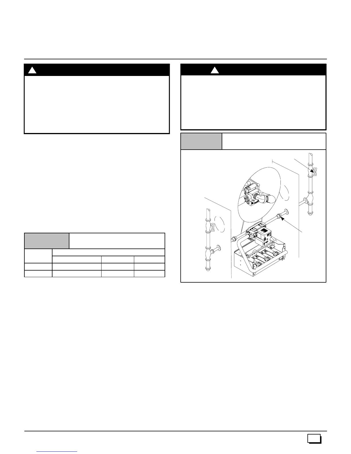
2. Itis recommendedthata manual equipment shutoff valve be
installed in the gas supply line outside the furnace. Locate
valveasclosetothefurnaceaspossiblewhereitisreadilyac-
cessible. Refer to Figure 12.
FIRE HAZARD
Failure to follow safety warnings exactly could
result in serious injury, death, and/or property
damage.
Use wrench to hold furnace gas control valve when
turning elbows and gas line to prevent damage to
the gas control valve and furnace.
!
W
RNING
Typical Gas Piping (N8MP)
Figure 12
Left entry
Right entry
Dipleg&pipecap
Left side entry
Union
Manual Equipment Shutoff Valve
25--24--36
3. Useblackironorsteelpipeandfittingsorotherpipeapproved
by local code.
4. Use pipe thread compound which is resistant to natural and
LP gases.
5. Use ground joint unions and install a drip leg no less than 3²
long to trap dirt and moisture before it can enter gas control
valve inside furnace.
6. Providea
1
/
8
² NPTpluggedtappingfortestgaugeconnection
immediately up stream of gas supply connection to furnace.
7. Usetwopipe wrencheswhenmaking connections toprevent
furnace gas control valve from turning.
NOTE:Iflocalcodesallowtheuseofaflexiblegasappliancecon-
nector,alwaysuseanewlistedconnector. Donotuseac onnector
which has previously served another gas appliance.
8. Flexible corrugated metal gas connector may NOT be used
inside the furnace or be s ecured or supported by the furnace
or ductwork.
9. Properly size gas pipe to handle combined appliance load or
run gas pipe directly from gas meter or LP gas regulator.
10. Install correct pipe size for run length and furnace rating.
11. MeasurepipelengthfromgasmeterorLPsecondstageregu-
lator to determine gas pipe size.