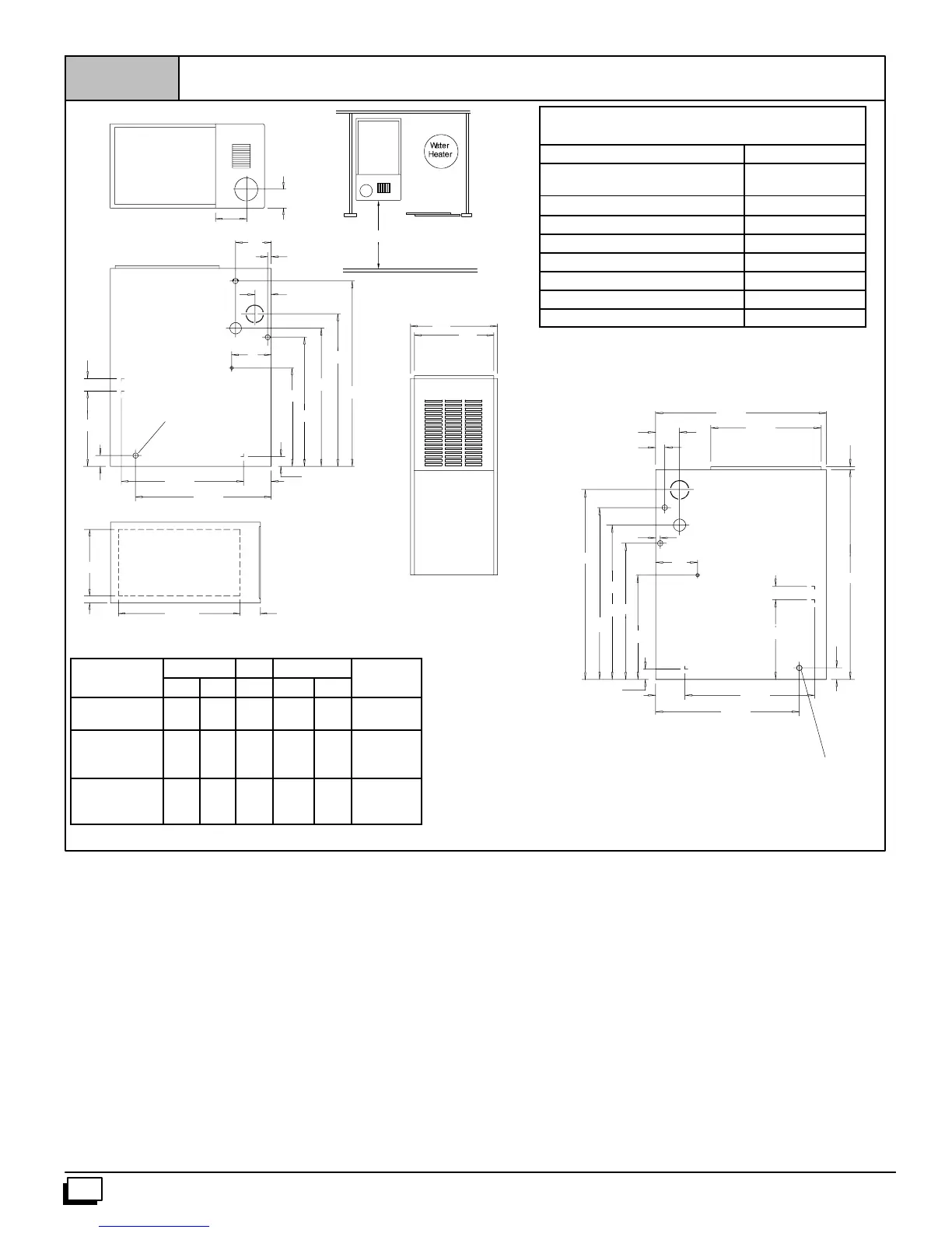
NOTE: Evaporator “A” coil drain pan dimensions may
vary from furnace duct opening size. Always consult
evaporator specifications for duct size requirements.
Furnace is designed for bottom return or side return.
Return air through back of furnace is NOT allowed.
17
5
/
16
30
3
/
4
29
1
/
2
2
1
/
4
3
3
/
4
27
1
/
2
17
5
/
16
2
1
/
4
Dimensions and Clearances (*8MPN/L Models)
Figure 2
Drawing is representative some models may vary
DIMENSIONS IN INCHES
7
33
7
2
1
/
2
21
3
/
4
LEFT SIDE
27
7
/
8
38
13
1
/
4
1
7
/
8
26
5
/
8
32
1
/
2
3
3
/
4
1
1
/
2
4
7
/
8
5
1
5
1
/
3
TOP
FRONT
A
B
F
30² Min.
13
1
/
4
RIGHT SIDE
28
1
/
2
18
1
/
2
3
/
4
7
1
40
21
3
/
4
4
7
/
8
26
5
/
8
1
7
/
8
1
1
/
2
37
BOTTOM
D
C
23
1
/
8
4
1
/
16
Plugged starting
hole to cut side
duct opening
Plugged starting hole to
cut side duct opening
H
J
6
441 01 2611 06
MINIMUM CLEARANCES TO COMBUSTIBLE
MATERIALS FOR ALL UNITS
REAR 0
FRONT (combustion air openings
in furnace and structure)
3²
Required For Service
*24²
ALL SIDES Of SUPPLY PLENUM 1²
SIDES 0
VENT
Single--Wall Vent 6²
Type B--1 Double Wall Vent 1²
TOP OF FURNACE 1²
*30² clearancerecommended forcasing removal.
Horizontalposition:Line contactispermissible onlybetween lines
formedby intersections oftop and two sidesof furnacejacket,and
buildingjoists,studs orframing.
DIMENSIONAL INFORMATION
Furnace
Cabinet Top Bottom
Return Air
Model
A B F C D
Opening
*8MPN/L050B12
*8MPN/L075B12
15
1
/
2
14 6 1
3
/
8
12
5
/
8
H
*8MPN/L075F16
*8MPN100F14
*8MPN/L100F20
19
1
/
8
17
5
/
8
7
3
/
4
2
1
/
8
14
3
/
4
J
*8MPN/L100J20
*8MPN/L125J20
*8MPN150J20
22
3
/
4
21
1
/
4
9
1
/
2
1
15
/
16
18
3
/
4
J
* Denotes Brand
Furnace Installation
Inspecttheratingplatetobec ertainthemodelnumberbeginswith
“N8MP” or“*8MP”.Thisidentifies theunitasamulti--positionfur-
naceandcanbeInstalledinaUpflow,HorizontalRight,Horizontal
Left or Downflow position.
Upflow
No modifications are required for upflow installation. (See
Figure 3)