29
441 01 2611 06
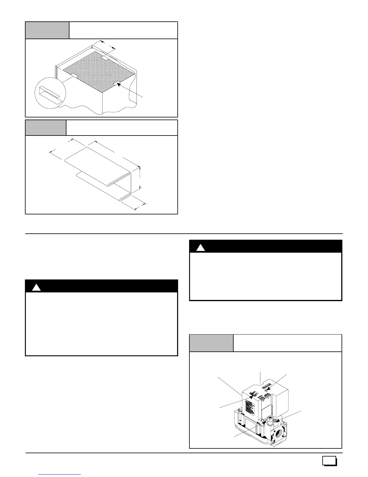
Figure 32
Top Mounted Internal Filter
9²
Center Clip
side --to -- side
Figure 33 Filter Clip Construction
3²
1
1
/
4
²
1
1
/
2
²
11
/
16
²
26 Ga. Galvanized Steel
NOTE: If filters are only s uitable for heating application, ad-
visehomeownerthatfiltersizemayneedtobeincreasedifair
conditioning is added.
Addition Of Air Conditioning
Whenarefrigerationcoili susedinconjunctionwiththisfurnace,it
mustbeinstalledonthedischargesideofthefurnacetoavoidcon-
densationontheheatexchanger.Thecoilinstallationinstructions
must be consulted for proper coil location and installation
procedures. With a parallel flow arrangement, dampers must be
installedtopreventchilledairfromenteringthefurnace.Ifmanual-
ly operated dampers are used, they must be equipped with a
means to prevent operation of either unit unless the damper is in
full heat or full cool position.
Copperorplastictubingmaybeusedforthecondensatedrainline.
12. Checks and Adjustments
Startup
NOTE: Refer to startup procedures in the Users Information
Manual.
!
ELECTRICAL SHOCK, FIRE, OR EXPLOSION
HAZARD.
Failure to follow safety warnings exactly could
result in serious injury, death, and/or property
damage.
If any sparks, odors or unusual noises occur,
immediately shut OFF gas and power to furnace.
Check for wiring errors or obstruction to blower.
WARNING
Gas Supply Pressure
Gassupplypressureshouldbewithinminimumandmaximumval-
ueslistedonrating plate.Pressuresareusuallysetby gassuppli-
ers.
(See LP Gas Conversion Kit instruction manualfor furnaces con-
verted to LP gas.)
Manifold Gas Pressure Adjustment
NOTE: Make adjustment to manifold pressure with burners oper-
ating.
!
FIRE OR EXPLOSION HAZARD.
FailuretoturnOFFgasatshutoffbeforeconnecting
manometer could result in death and/or personal
injury.
Turn OFF gas at shut off before connecting
manometer.
W
RNING
1. With gas OFF,connect manometerto manifoldpressure tap
onoutletofgascontrolvalve.SeeFigure 34.Useamanome-
terwitha0² to 12² water column range.
Typical Gas Control Valve Honeywell
Figure 34
INLET
OUTLET
Diagnostic Light
(on some models)
25--22--25a
On/Off
Switch
Pilot Pressure
Adjustment
Manifold Pressure
Adjustment
(Hidden)
Manifold
Pressure
Tap
Supply Pressure
Tap (Hidden)