28
441 01 2611 06
removingtheknockoutpanelinthefurnacebase. Return air con-
nectionthrough theside(s)orback ofthe furnace is NOT allowed.
Duct Design
Designandinstallairdistributionsystemto complywithAirCondi-
tioning Contractors of America manuals or other approved meth-
ods that conform to local codes and good trade practices.
Whenthefurnaceislocatedinanareanearoradjacenttotheliving
area,thesystemshouldbecarefullydesignedwithreturnstomini-
mize noise transmission through the return air grille. Any blower
movingahighvolumeofairwillproduceaudiblenoise,whichcould
beobjectionablewhenthefurnaceislocatedvery closetoaliving
area. It is often advisable to route the return air ducts under the
floor or through the attic.
· RefertofurnaceTechnicalSupportManual(BlowerData)
for air flow information.
· Size ductwork to handle air flow for heating (and air condi -
tioning, if so equipped).
Duct Installation Requirements
· Whenafurnaceisinstalledsothatsupplyductscarryaircir-
culatedbythefurnacetoareasoutsideofthespacecontain-
ing the furnace, the return air shall also be handled by
duct(s)sealedtothefurnacecasingandterminatingoutside
the space containing the furnace.
CARBON MONOXIDE POISONING HAZARD.
Failure to follow safety warning exactly could
result in serious injury, death, and/or property
damage.
Install cooling coil on furnace discharge. Cool air
passing over heat exchanger could cause
condensate to form resulting in heat exchanger
failure.
!
WARNING
· Whenafurnace isusedwithacoolingunit,thefurnaceshall
beinstalledparallelwithorontheupstreamsideofthecool-
ing unit to avoid condensation in the heating element.
· With a parallel flow arrangement, the dampers or other
means used to control flow of air shall be adequate to pre-
vent chilled air fromentering the furnace. Chilled air going
throughthefurnacecouldcausecondensationandshorten
furnacelife. Dampers(purchasedlocally)canbeeitherau -
tomatic or manual. Manually or automatically operated
dampers MUST be equipped with a means to prevent fur-
naceand airconditioningoperation,unlessdamperisinthe
full heat or cool position.
· Installationoflocking--typedampersis recommendedinall
branches, or in individual ducts to balance system’s air
flows.
· Non--combustible, flexible duct connectors are recom-
mended for return and supply connections to furnace.
· If air return grille is located close to the fan inlet, install at
least one 90° air turn between fan and inlet grille to reduce
noise.
· Ductwork installed in attic or exposed to outside tempera-
tures requires a minimum of 2² of insulation with outdoor
type vapor barrier.
· Ductwork installed in an indoor unconditioned space re-
quires a minimumof 1² of insulation with indoor type vapor
barrier.
Filters
A filter MUST be used.
Filtersarenotsuppliedwiththesefurnaces,butcanbepurchased
from your distributor.
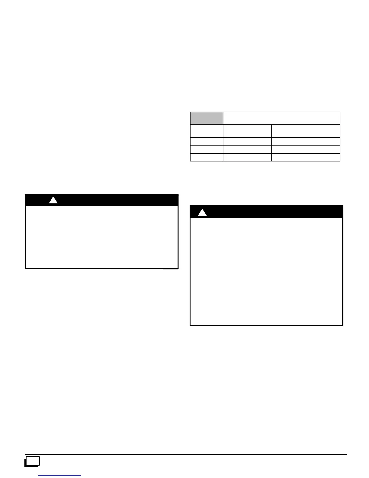
See Table 6 for required high--velocity filter sizes.
Table 6 High Velocity Air Filter Sizes (max. 600 FPM)
Cabinet
Width
Internal Filter External Filter Rack
15
1
/
2
²
²²
² 14² X25² 14² X25²
19
1
/
8
²
²²
² 16² X25² 16² X25²
22
3
/
4
²
²²
² 20² X25² 20² X25²
Use either filter type:
· Washable,high--velocityfiltersarebasedonamaximumair
flow rating of 600 FPM.
· Disposable,lowvelocityfiltersarebasedonamaximumair
flow of 300 FPM when used with external filter grille.
!
REDUCED FURNACE LIFE HAZARD
Failure to follow caution instructions may result in
reduced furnace life.
Use of excessively dirty and/or restrictive air filters
may increase furnace operating
temperatures and shorten the life of the furnace.
Filters supplied with the furnace are rated at a
maximum of 600 fpm air velocity and sized for the
furnace’s airflow rate. Replacement filters must be
of equivalent type, size, and rating except as
described below.
Disposable, low--velocity filters may be used to
replace washable, high--velocity filters, providing
they are sized for 300 FPM or less.
C
UTION
NOTE: Disposable, low--velocity filters may be replaced with
washable, high--velocity filters. Washable, high--velocity filters
canbereplacedONLYwithsametypeand sizefilters unlesslow--
velocity filters meetthe minimum size areas for 300 FPM or less.
Internal Filter in Top Return Installation
Wheninstallingtop--mountedfilterinsidethefurnace,installthefil-
ter c lips on the edge of the top duct opening with the wider end of
the clips toward the blower as shown in Figure 32. Clips may be
obtained from your distributor or fabricated from sheet metal
(Figure 33). Insertfilterintosideclipsfirstandpushfilterbackuntil
it is fully engaged into back clip.