22
441 01 2611 06
9. Electrical Wiring
ELECTRICAL SHOCK HAZARD.
Failure to follow safety warnings exactly could
result in serious injury, death, and/or property
damage.
Turn OFF electrical power at fuse box or service
panel before making any electrical connections
and ensure a proper ground connection is made
before connecting line voltage.
!
WARNING
Power Supply Wiring
The furnace MUST be electrically wired and grounded in accor -
dance with local codes, or in the absence of localcodes, with the
NationalElectricalCode(NEC),ANSI/NFPA70--2002 in the U.S.,
or the Canadian Electrical Code (CEC), CSA C22.1 in Canada.
The power supply to the furnace connections must be between
104 VAC and 127 VAC during furnace operation for acceptable
performance.
Fieldwiringconnectionsmustbemadeinsidethefurnaceconnec-
tion box. A suitable strain relief should be used at the point the
wires exit the furnace casing.
Copper conductors shall be used. Line voltage wires should
conform to temperature limitation of 63° F(35° C) rise. Wire and
circuitbreakersizingshallbebasedontheampacityofthefurnace
electrical components plus the amps for all installed accessories
(0.8 amps total for EAC and HUM). Ampacity can be determined
by using the NEC or CEC.
Furnace must be installed so the electrical components are pro-
tected from water and connected to its own separate circuit.
J-Box Relocation
N8MPN and N8MPL Models
TheJ--boxisinstalledinblowercompartmentonleftsideofcasing.
An alternate J--box location on right side can be used.
1. Removebag containing two hole plugs and two self--tapping
screws from loose parts bag in blower compartment.
2. Remove and discard two screws holding J--box to casing.
3. Move large hole plug from right to left J--box location.
4. Move J--box to alternate location and attach using two self--
tapping screws from bag.
5. Apply two hole plugs from bag at left J--box location.
6. Position all wires away from sharp edges and moving parts.
Do not pinch J--box wires or other wires when reinstalling
blower compartment door.
*8MPN and *8MPL Models
The J--box is installed in the burner compartment on left side of
casing. An alternate J--box location on right side can be used:
1. Remove and save two screws holding J--box to casing.
2. Move large hole plug from right to left J--box location.
3. MoveJ--boxtoalternatelocationandattachusingtwoscrews
removed from left side location.
4. Position all wires away from hot surfaces, sharp edges, and
moving parts. Do not pinch J--box wires or other wires when
reinstalling burner compartment door.
Thermostat
Thermostatlocationhasanimportanteffectontheoperationofthe
furnace. Follow instructions included with thermostat for correct
mounting and wiring.
Low voltage connections to furnace must be made on terminal
board to fan control. (See Figure 19)
Ifcoolingisused,theY fromthethermostatmustbe connectedto
the control board Y to energize cooling blower speed.
Set thermostat heat anticipator in accordance with the Technical
Support Manual.
Optional Equipment
AllwiringfromfurnacetooptionalequipmentMUST conformtolo-
calcodesor,intheabsenceoflocalcodes,theapplicablenational
codes. Install wiring in accordance with manufacturer’s instruc-
tions.
Humidifier/Electronic Air Cleaner
The furnace is wired for 115 VAC humidifier and/or electronic air
cleaner connection.
NOTE:
Do NOT exceed 115V/0.8 amp. maximum current
load for both the EAC terminal and the HUM terminal
combined.
NOTE: The humidifier will be powered when the furnace is fired
andthe circulatingairblowercomeson.Theelectronicaircleaner
will be powered anytime the thermostat calls for air movement.
However, the electronic aircleaner is NOT energized during c on-
tinuous fan operation controlled by the electronic fan control.
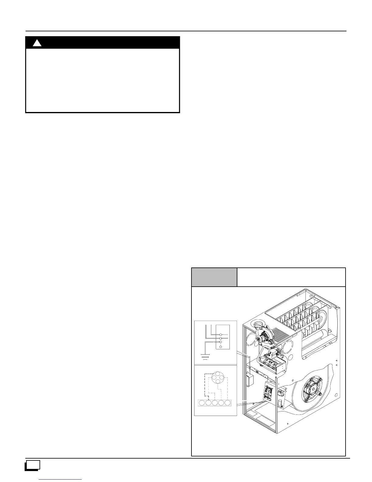
Figure 19
Electrical Connections
NOTE: 115 VAC/60Hz/single--phase
Operating voltage range*: 127 max, 104 min.
* Permissible limits of voltage at which unit will operate satisfactorily
115V. 60Hz.
W
BK
G
Connection
Box
Ground
HOT
NEUT.
Thermostat
Low Voltage
TerminalBoard
R
G
G
Y
R
Y
W
W
C
25--24--33--4