8
441 01 2611 06
10. Installburnercompartmentdooronfurnacewithbeveledgeat
bottom.
N8MPN/L, C8MPN/L, H8MPN/L
1. Carefully remove logo from burner compartment door and
save it.
2. Turn the logo rightside--up, and install the logo retainer pins
into holes in burner compartment door.
3. New labels for rightside--up application on outside of blower
compartmentdoormaybepurchasedinakitfromyourdistrib-
utor to cover upside--down labels.
Downflow Venting: The combustion venter MUST be rotated to
ventoutthes ideforalldownflowinstallations,(seeFigure 5).Bot-
tomventingisnotpermitted.See“Sideventing”forinstructionsto
rotatetheventtothes ide.Inadditiontorotatingtheventtothes ide
a Vent Pipe Shield (NAHA002VC) is required to shield the hot
vent pipe.
!
BURN HAZARD.
Vent pipe is HOT and could cause personal injury.
Hot vent pipe is in reach of small children when
installed in downflow position.
Install vent pipe shield NAHA002VC.
WARNING
Pressure Switch Relocation
Ifthefurnaceisinstalledintheupflowposition,thepressureswitch
will remain in the sameposition as installed by the factory unless
the inducer is rotated. If the furnace is installed in an orientation
that places the pressure switch below the pressure tap on the in-
ducerhousing,thentheswitchMUST berelocated. In order tore-
locatetheswitch,locate2mountingholesordrillabovetheinducer
pressure tap. When drilling the 2 holes make sure to keep the
switch and tubing far enough away from the burners or hot sur -
facesastonotmeltthehose,switch,orwires.Topreventpossible
kinking of the pressure switch hose, trim the hose to remove ex-
cess length.
Note:Whendrillingnewholesmakesuremetalshavingsdonotfall
on or in components, as this can shorten the life of the furnace.
See side venting
for venter rotation
Typical Downflow Installation
Figure 5
VENT
GAS SUPPLY
MUST BE OPPOSITE
VENT DISCHARGE
SIDE
SUPPLY
AIR
RETURN
AIR
OPTIONAL VENT
25--23--19
Combustible floor
base outlet flange
adapter
Vent Shield
Kit
3. Side Venting
This furnace is shipped from the factory with the venter assembly
in an upflow configurations (top vent). The venter assembly can
easily be rotated to a side vent configurations for use in upflow,
horizontal--flow, or downflow application.
When using a side vent configuration (side outlet instead of top
outlet),it may be necessary to relocate the pressure switch to the
alternatepositionontheoppositesideofthetoppanel. Twoscrew
holes are provided at the alternate position. Route the pressure
switch tubing so the tubing is not kinked and not touching the hot
collector box, venter housing, or motor. It may be necessary to
shorten the length of the tubing to properly route the tubing and
eliminate kinks.
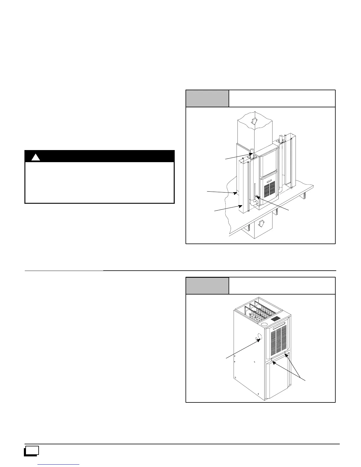
Rotating the Venter Assembly
1. If gas and electrical power have already been connected to
unitshutoffgasandremovepowerfromunit.Unscrewscrews
onburnercompartmentdoorandremoveburnercompartment
door. See Figure 6.
2. Disconnectpowerleads totheventermotorandhosetopres-
sureswitch.Removethree(3)orfour(4)screwswhichsecure
the venter to the collector box, (see Figure 7).
3. Cut webbing with a pair of snips holding the vent plate to the
cabinetoneithertheleftorrightsideofunitdependingonright
or left venting as desired. Discard vent plate, (see Figure 6).
Figure 6
25--23--45
Screws (2)
Furnace with Screws
Vent Plate