7
441 01 2611 06
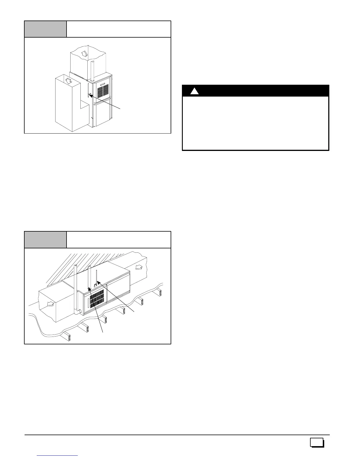
Typical Upflow Installation
Figure 3
25--23--17
VENT
SUPPLY
AIR
GAS SUPPLY
RETURN
AIR
Horizontal
Ifyou purchaseda multi --position furnace,it can be installed hori-
zontallyin an attic, basement,crawlspace,alcove, or suspended
from a ceiling in a basement or utility room in either a right or left
airflow position. (see Figure 4)
Horizontally installed furnaces may be vented out the top of the
unitoroutthesidefacingup.See“Sideventing”forinstructionsto
rotate the vent to the side.
The minimum clearances to combustibles MUST be maintained
between the furnace and adjacent construction, as shown in
Figure 1 and Figure 2. ONLYthecornerofthecabinet is allowed
to contact the rafters as shown in Figure 4. All other clearances
MUST be observed as shown in Figure 1 and Figure 2.
Typical Horizontal Installation
Figure 4
VENT
VENT
GAS SUPPLY
SUPPLY
AIR
RETURN
AIR
25-23-18a
OPTIONAL
VENT LOCATION
Ifthefurnaceistobesuspendedfromthefloorjoistsinabasement
orcrawlspaceortheraftersinanattic,itis necessary to use s teel
pipe straps or an angle iron frame to attach the furnace. These
straps should be attached to the furnace bottom side with sheet
metal screws and to the rafters or joists with bolts. The preferred
methodistouse an angle ironframe bolted to therafters or joists.
Ifthefurnaceistobeinstalledatgroundlevelinacrawlspace,con-
sult local codes. A concrete pad 1² to 2² thick is recommended.
Thirtyinches(30²)isrequiredbetweenthefrontofthefurnaceand
adjacent construction or other appliances. This should be main-
tained for service clearance.
Keep all insulating materials clear from louvered door. Insulating
materials may be combustible.
The horizontal furnaces may be installed directly on combustible
woodflooringorsupports, however,it is recommendedforfurther
fireprotectioncementboardor sheetmetalisplacedbetweenthe
furnace and the combustible wood floor and extend 12² beyond
the front of the furnace louver door. (This is a recommendation
only, not a requirement).
This furnace MUST NOT be installed directly on carpeting, tile or
other combustible material other than wood flooring or supports.
Downflow
FIRE HAZARD.
Failure to install unit on noncombustible subbase
couldresultin death,personalinjuryand/orproperty
damage.
Place furnace on noncombustible subbase on
downflow applications, unless installing on
noncombustible flooring.
!
W
RNING
If you purchased a Multi--position furnace (*8MP) it may be
installed in a downflow configuration, (see Figure 5). The mini-
mumclearancestocombustionconstructionMUSTbemaintained
between the furnace and adjacent construction, as shown in
Figure 1 and Figure 2.
In addition to clearances in Figure 1 and Figure 2, clearance for
the vent pipe must be considered.
As ubbaseforcombustiblefloorsMUSTbeusedwhenthefurnace
isinstalledasadownflowoncombustiblematerial. See11.“Duct-
work and Filter” (Downflow Section). The outlet flange must be
bent flat for downflow installation.
When installing a four--position furnace in the downflow position
(not the *8DNLfurnace),the logo is to be repositioned s o that it is
rightside--up as follows:
T8MPN/L
1. Find the door hardware k it that is stored in the furnace and
save it.
2. Carefullyremovelogofromtheoutsideofburnercompartment
door and save it.
3. Carefullyremovetwos mall plugbuttonsfromoutsideofblow-
er compartment door and save them.
4. Removetwo thumbscrews from blower c ompartment door by
cutting apart metal retainer washers on inside of door with
smalldiagonalcuttingpliers.Theretainer washerswillnotun-
screwfromthe thumbscrews.Savethetwo thumbscrewsand
two plastic washers.
5. Install two thumbscrews in holes at other end of blower
compartment door from where thumbscrews were removed.
a. A plastic washer should be on each of the two thumb-
screwsbeforeinsertingthe thumbscrewsintotheblower
compartment door holes.
b. After inserting each thumbscrew into the proper hole in
the blower door, push a new metal retainer washer onto
each thumbscrew as far as it will go.
6. Install newstrip of rubber gasketon inside of blowercompart-
ment door on edge that does not already have a gasket.
7. Installlogoretainerpinsintoholesinblowercompartmentdoor
from which plug buttons were removed.
8. Installplugbuttonsintoholesinburnercompartmentdoorfrom
which logo was removed.
9. Install blower compartment door on furnace with bevel edge
and logo at top.