24
441 01 2611 06
· Installation of locking-type dampers is recommended in all
branches,orinindividualducts tobalancesystem’sairflows.
· Non--combustible, flexible duct connectors are recom-
mended for return and supply connections to furnace.
· Ifairreturngrilleislocatedclosetothefaninlet,installatleast
one 90° air turn between fan and inlet grille to reduce noise.
· Ductworkinstalledinatticorexposedtooutsidetemperatures
requiresaminimumof2² ofinsulationwithoutdoortypevapor
barrier.
· Ductworkinstalledinanindoorunconditionedspacerequires
a minimum of 1 ² of insulation with indoor type vapor barrier.
Inspection Panel on some models
Forafurnacenotequippedwithacoolingc oil,theoutletductshall
beprovidedwitharemovableaccesspanel. Thisopeningshallbe
accessiblewhenthefurnaceisinstalledandshallbeofs uchasize
thattheheatexchangercanbeviewedforpossibleopeningsusing
light assistance or a probe can be inserted for sampling the air
stream. This access cover shall be attached in such a manner as
to prevent air leaks.
Filters
A filter MUST be used.
Filtersarenotsupplied
withthesefurnaces,butcanbepurchased
from your distributor.
See Table 4 for required high--velocity filter sizes.
Table 4
High--Velocity Air Filter Sizes (max.600 FPM)
Cabinet
Internal Filter External Filter Rack
Width
Bottom Bottom Side+
15
1
/
2
14X25 14X25 14X25 or 16X25
19
1
/
2
16X25* 16X25* 16X25*
22
3
/
4
20X25* 20X25* 16X25*
* Greater than 1600 CFM requires both (left and right) side return filter
racks in upflow position.
+Sidereturnairduct(s)isnotpermittedwithhorizontalordownflowfurnace
installation.
Use either filter type:
· Washable,high--velocityfiltersarebasedonamaximumair
flow rating of 600 FPM.
· Disposable,lowvelocityfiltersarebasedonamaximumair
flow of 300 FPM when used with external filter grille.
!
RISK OF REDUCED FURNACE LIFE
Failure to follow these Caution may result in
premature furnace component failure.
Use of excessively dirty and/or restrictive air filters
may increase furnace operating temperatures and
shorten the life of the furnace.
Filters specified for the furnace are rated at a maximum
of 600 FPM air velocity and sized for the furnace’s
airflow rate. Replacement filters must be of equivalent
type, size, and rating except as described below.
Disposable, low--velocity filters may be used to replace
washable, high--velocity filters, providing they are sized
for 300 FPM or less.
C
UTION
· The furnaces with 1600 or less CFM rating use a 16” x 25”
high--velocity filter. On these models the filter may be
mountedinternallyforbottomreturn ora filter and rackmay
be mounted externally for bottom return.
· The furnaces withgreater than 1600 CFM require that both
(left and right) side returns are used. Two side return filters
andracksarerequired.Filterracks mustbemountedexter-
nally. See Figure 24.
· If return air must be on one side only, an optional 20² x25²
filterstandoffrackkitcanbeused.(SeeFigure 22.)Forbot-
tomreturn,aninternalfiltercanbeusedorafilterrackkitcan
be mounted externally.
NOTE:The20 ² x25² standoffs idefilterrackgivesmorefilterarea
but does not provide more air. See Figure 22. To achieve 2000
CFM 2 side returns are still needed. See Figure 24.
NOTE: Disposable low--velocity filters may be replaced with
washable,high--velocityfilters.Washable,high--velocityfilterscan
bereplacedONLYwithsametypeandsizefilterunlesslow--veloc-
ity filters meet the minimum size areas for 300 FPM or less.
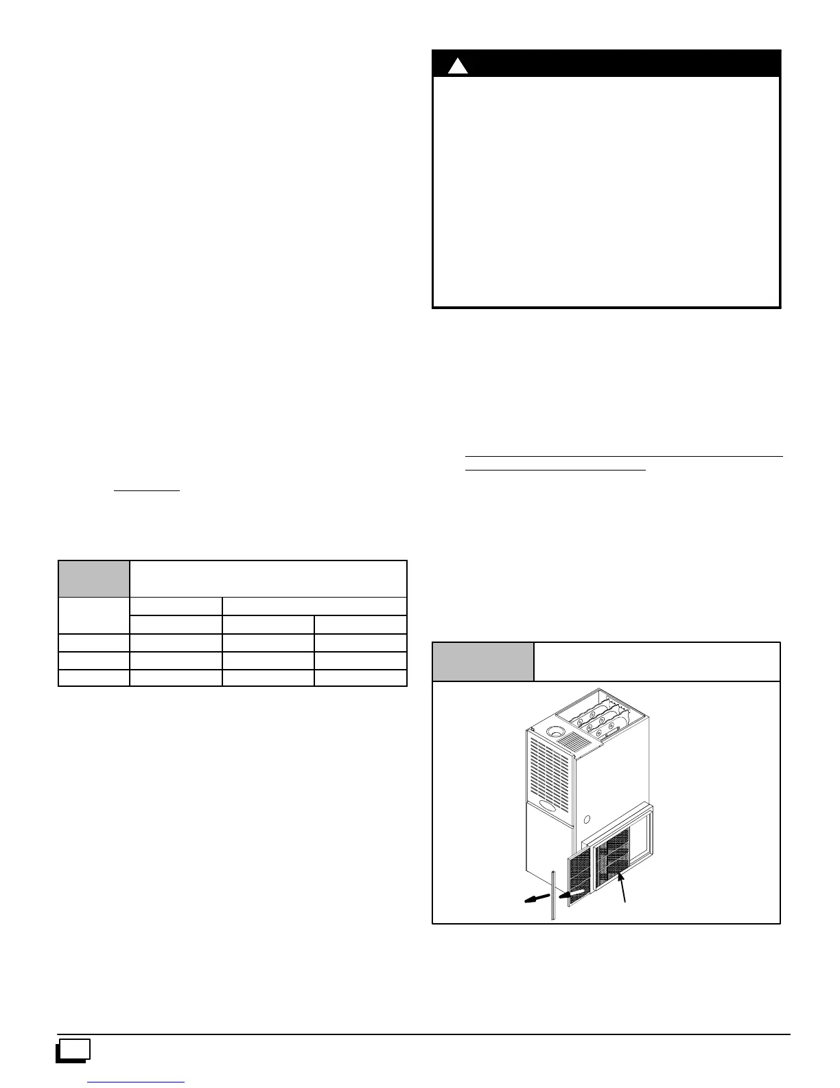
Figure 22
Optional Duct Standoff
20x25Optional
Filter Rack
Filter
25--23--05--4
Optional Filter Rack Installation: Side Return
Centerthefilterrackonthesidepanel,flushwiththebottomedge
ofthefurnace. Mark the fastening holes. Drillthe fastening holes
inthes idepanelandfastenthefilterrackinplacewithsheetmetal
screws. See Figure 23 and Figure 24.