26
441 01 2611 06
BURN HAZARD.
The vent may be hot. Failure to install vent shield
properly could result in bodily injury.
Install VENT PIPE SHIELD NAHA002VC as
described below.
!
WARNING
Vent Shield
Ventshieldisrequiredforalldownflowinstallations.TheventMust
exit out the side of the furnace for all downflow installations. This
placesthehotventpipe(over300° F)withinreachofchildren.Vent
shieldattachestosideoffurnacetocoverventpipe.SeeFigure 5
in “2. Installation” section.
Outlet Duct Flange
Downflow installations with cased coils require the furnaceoutlet
ductflangetobebentoutwardandflattomatetheoutletofthefur -
nacetothecasedcoil.
FIRE HAZARD.
Failure to install furnace on noncombustible
subbasecouldresultin death,personalinjuryand/or
property damage.
Place furnace on noncombustible subbase on
downflow applications, unless installing o n
non--combustible flooring.
!
WARNING
Sub--Bases for Combustible Floors -- Furnace Only
Note: When using the subbase for combustible floors, the dis-
charge air duct flanges on the furnace MUST be broken down to
provide proper fit up to the subbase. Use duct pliers to bend the
duct flanges flat onto the furnace casing. DO NOT bend the duct
flanges inward (toward the heat exchangers) as air flow restric-
tions may occur.
The Subbase for Combustible Floors MUST be used when a
downflowfurnaceissetonacombustiblefloor,evenwhenthefur-
nace is installed on a coil box.
1. Cut the opening in the floor according to the dimensions in
Table 5 because thebase is equipped withlocating tabs that
center the base over the opening.
The opening in the base is 1
1
/
4
² shorter and 1
1
/
8
² narrower
than the minimum required size of the opening in the floor.
Thisisdonetomaintaina1² clearance betweenthefloorand
the plenum.
2. Fabricate the plenum to the dimensions given in Table 5.
Note that the dimensions given are outside dimensions.
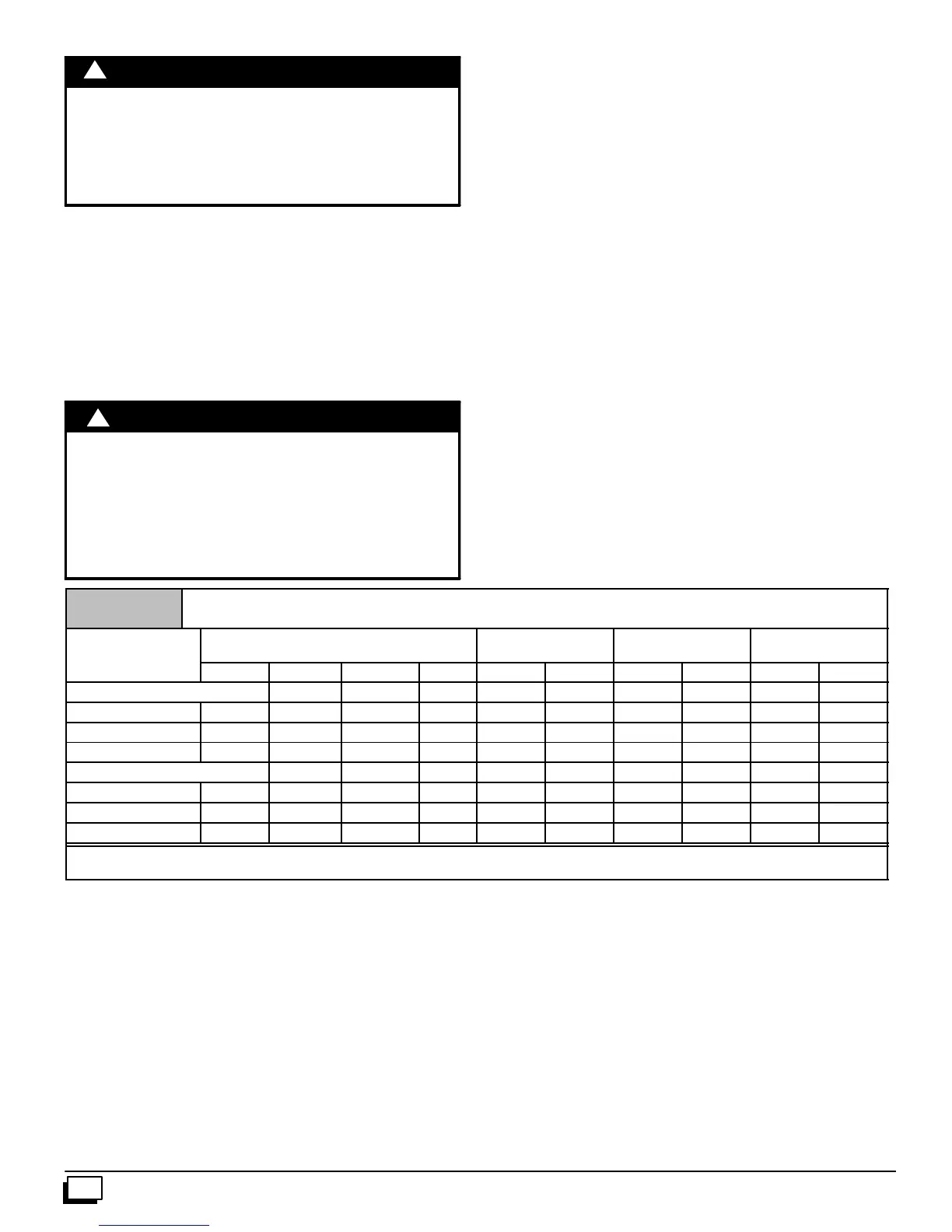
Table 5
Sub--bases for Combustible Floors Dimensions
Sub--base for
Combustible Floors
Sub--base for Combustible
Floor Dimensions
OpeningInFloor
Opening In
Base For Plenum
Typical Plenum
Dimensions
Part Number
H
*
J* K** L M N P R S T
Subbase for Furnace Only
NAHH001SB 15
11
/
16
28
3
/
4
14
9
/
16
16 16
1
/
4
14
5
/
8
15 13
1
/
2
15 13
1
/
2
NAHH002SB 19
5
/
16
28
3
/
4
18
3
/
16
16 16
1
/
4
18
1
/
4
15 17
1
/
8
15 17
1
/
8
NAHH003SB 22
15
/
16
28
3
/
4
21
13
/
16
16 16
1
/
4
21
7
/
8
15 19
3
/
4
15 19
3
/
4
Subbase for Coil Box
NAHH004SB 15
11
/
16
20
9
/
16
14
9
/
16
16 16
1
/
4
14
5
/
8
15 13
1
/
2
15 13
1
/
2
NAHH005SB 19
5
/
16
20
9
/
16
18
3
/
16
16 16
1
/
4
18
1
/
4
15 17
1
/
8
15 17
1
/
8
NAHH006SB 22
15
/
16
20
9
/
16
21
13
/
16
16 16
1
/
4
21
7
/
8
15 19
3
/
4
15 19
3
/
4
*
Outside Dimension
**
Base Spacer Side To Side
3. Setthebaseovertheopeninginthefloor,centeringtheopen-
inginthebaseovertheopeninginthefloor.Fastenthebaseto
the floor with screws or nails. See Figure 27 and Figure 28.
4. Droptheplenumthrough the opening inthebase. Theflange
oftheplenumshouldrestontopofthecombustiblefloorbase.