I Electric Furnace
CondensateDrain
Installation Instructions
The unit is provided with 3/4" National Pipe Thread (NPT) con-
densate drains. (Figure 1). Any drain can be used as a primary or
secondary drain. Condensate drain lines should be installed in a
manner that does not obstruct access to the filter.
There is a secondary drain fitting supplied with the unit that will
convert any of the primary condensate drain connections into a
secondary drain connection. This fitting should be installed in any
of the primary drain connections to convert itto a secondary drain.
1. Connect the drain lines to the appropriate drain fittings. 3/4"
PVC or other type of drain line may be used. The drain line
must not be smaller than the drain fitting.
2. Install a trap in the drain line below the bottom of the drain
pan and pitch the drain lines down from the coil at least I/4"
per foot of run. Horizontal runs over 15 feet long must also
have an anti-siphon air vent (stand pipe), installed ahead
of the horizontal run. An extremely long horizontal run may
require an oversized drain line to eliminate air trapping.
3. Route to the outside or to a floor drain, laundry tray or waste
line (sewer). Check local codes before connecting to a
sewer line.
4. Insulate drain lines where sweating could cause water
damage.
5. If a gravity drain cannot be used, install a condensate
pump. Install the pump as close to the indoor section as
possible.
SpecialNote For DownflowInstallations
For downflow installations, a secondary overflow drain
connection must be installed to prevent water from dripping onto
live electrical components. Use the secondary fitting on the
evaporator coil.
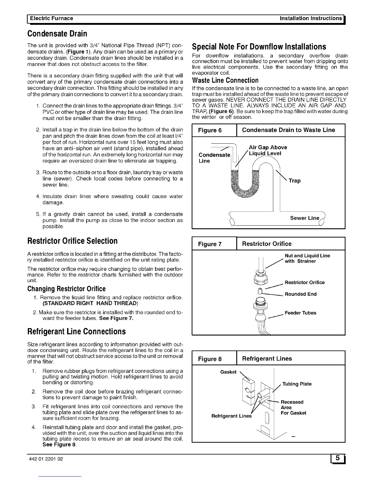
Waste Line Connection
If the condensate line is to be connected to a waste line, an open
trap must be installed ahead of the waste line to prevent escape of
sewer gases. NEVER CONNECT THE DRAIN LINE DIRECTLY
TO A WASTE LINE. ALWAYS INCLUDE AN AIR GAP AND
TRAP, (Figure 6). Be sure to keep the trap filled with water during
the winter or off season.
Figure 6 J Condensate Drain to Waste Line
Air Gap Above
Condensate uid Level
Line
Sewer Line_-_
RestrictorOrificeSelection
A restrictor orifice is located in a fitting at the distributor. The facto-
ry installed restrictor orifice is identified on the unit rating plate.
The restrictor orifice may require changing to obtain best perfor-
mance. Refer to the restrictor charts furnished with the outdoor
unit.
Changing RestrictorOrifice
1. Remove the liquid line fitting and replace restrictor orifice.
(STANDARD RIGHT HAND THREAD)
2. Make sure the restrictor is installed with the rounded end to-
ward the feeder tubes. See Figure 7.
RefrigerantLine Connections
Figure 7 J Restrictor Orifice
Nut and Liquid Line
Jwith Strainer
Restrictor Orifice
_--_ Rounded End
/FeederTubes
Size refrigerant lines according to information provided with out-
door condensing unit. Route the refrigerant lines to the coil in a
manner that will not obstruct service access to the unit or removal
of the filter.
1. Remove rubber plugs from refrigerant connections using a
pulling and twisting motion. Hold refrigerant lines to avoid
bending or distorting.
2. Remove the coil door before brazing refrigerant connec-
tions to prevent damage to paint finish.
3. Fit refrigerant lines into coil connections and remove the
tubing plate and slide plate over the refrigerant lines to as-
sure sufficient room for brazing.
4. Reinstall tubing plate and door and install the gasket, pro-
vided with the unit, over the suction and liquid lines into the
tubing plate recess to ensure an air seal around the coil.
See Figure 8.
I
Figure 8 J Refrigerant Lines
Gasket
Plate
Recessed
Area
For Gasket
442 01 2201 02 W