I Blower Coils Installation Instructions
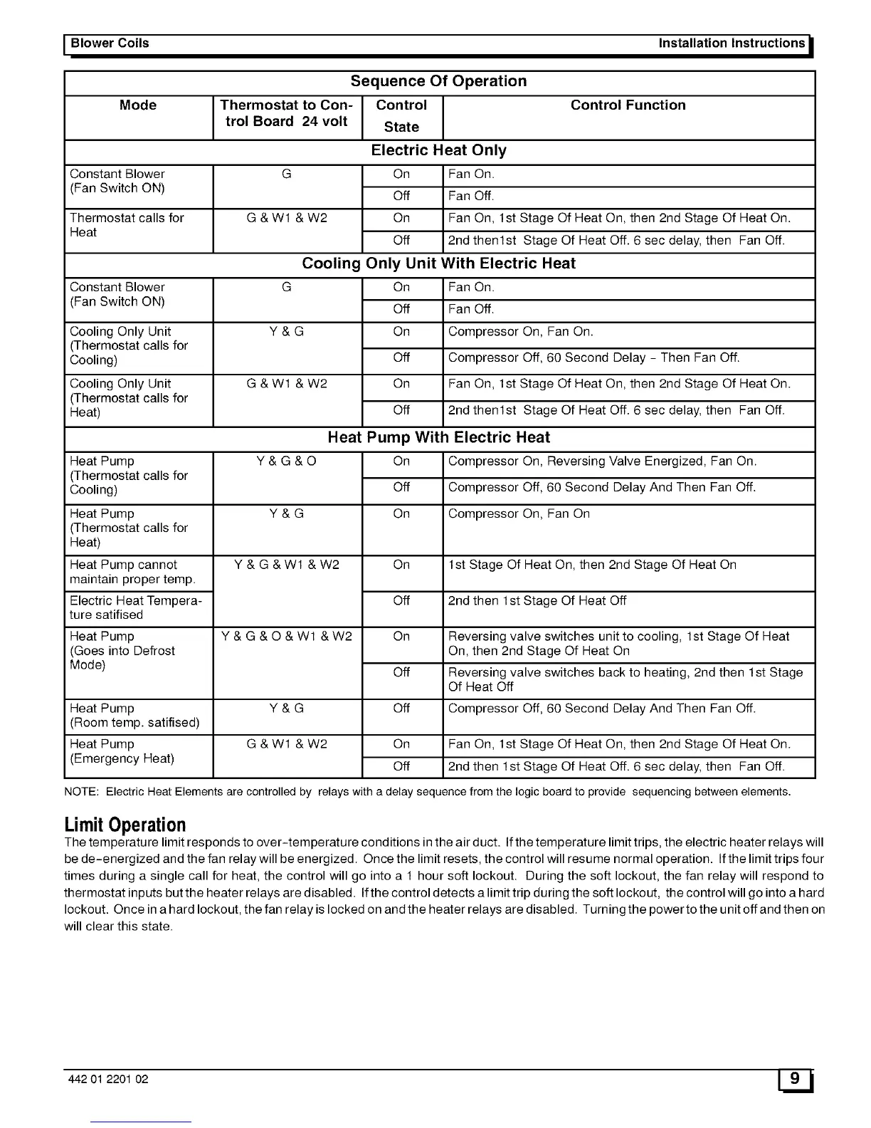
Sequence Of Operation
Mode |Thermostat to Con- | Control Control Function
trol Board 24 volt [ State
Electric Heat Only
Constant Blower
Fan Switch ON)
Thermostat calls for
Heat
Constant Blower
Fan Switch ON)
Cooling Only Unit
(Thermostat calls for
Cooling)
Cooling Only Unit
(Thermostat calls for
Heat)
Heat Pump
(Thermostat calls for
Cooling)
G
G&W1 &W2
G
Y&G
G&W1 &W2
Y&G&O
Heat Pump Y & G
(Thermostat calls for
Heat)
Y&G&Wl &W2
On
Off
On
Off
Cooling Only
Fan On.
Fan Off.
Fan On, 1st Stage Of Heat On, then 2nd Stage Of Heat On.
2nd thenlst Stage Of Heat Off. 6 sec delay, then Fan Off.
Unit With Electric Heat
Heat Pump cannot
maintain proper temp.
Electric Heat Tempera-
ture satifised
Heat Pump
(Goes into Defrost
Mode)
On
Off
On
Off
On
Off
Heat Pump With
Fan On.
Fan Off.
Compressor On, Fan On.
Compressor Off, 60 Second Delay - Then Fan Off.
Fan On, 1st Stage Of Heat On, then 2nd Stage Of Heat On.
2nd thenlst Stage Of Heat Off. 6 sec delay, then Fan Off.
Electric Heat
Heat Pump
Room temp. satifised)
Heat Pump
(Emergency Heat)
Y&G&O&W1 &W2
Y&G
G&W1 &W2
On
Off
On
On
Off
On
Off
Off
On
Off
Compressor On, Reversing Valve Energized, Fan On.
Compressor Off, 60 Second Delay And Then Fan Off.
Compressor On, Fan On
1st Stage Of Heat On, then 2nd Stage Of Heat On
2nd then 1st Stage Of Heat Off
Reversing valve switches unit to cooling, 1st Stage Of Heat
On, then 2nd Stage Of Heat On
Reversing valve switches back to heating, 2nd then 1st Stage
Of Heat Off
Compressor Off, 60 Second Delay And Then Fan Off.
Fan On, 1st Stage Of Heat On, then 2nd Stage Of Heat On.
2nd then 1st Stage Of Heat Off. 6 sec delay, then Fan Off.
NOTE: Electric Heat Elements are controlled by relays with a delay sequence from the logic board to provide sequencing between elements.
LimitOperation
The temperature limit responds to over-temperature conditions in the air duct. If the temperature limit trips, the electric heater relays will
be de-energized and the fan relay will be energized. Once the limit resets, the control will resume normal operation. If the limit trips four
times during a single call for heat, the control will go into a 1 hour soft lockout. During the soft lockout, the fan relay will respond to
thermostat inputs but the heater relays are disabled. Ifthe control detects a limit trip during the soft lockout, the control will go into a hard
lockout. Once in a hard lockout, the fan relay is locked on and the heater relays are disabled. Turning the power to the u nit off and then on
will clear this state.
442 01 2201 02 W