440 01 4300 00 19
Specifications subject to change without notice.
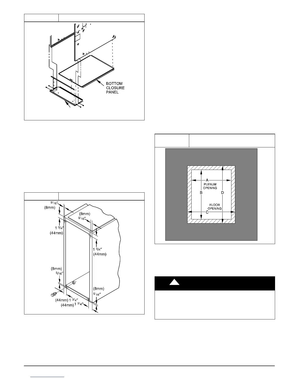
Figure 19 Removing Bottom Closure Panel
L11F004
BOTTOM
PLATE
Side Return Air Inlet
These furnaces are shipped with bottom closure panel installed
in bottom return−air opening. This panel MUST be in place
when only side return air is used.
NOTE: Side return−air openings can be used in UPFLOW and
most HORIZONTAL configurations. Do not use side return−air
openings in DOWNFLOW configuration. (See Figure 27,
Figure 28 and Figure 29)
Leveling Legs (If Desired)
In upflow position with side return inlet(s), leveling legs may be
used. (See Figure 20) Install field−supplied, 5/16 x 1−1/2 in. (8
x 38 mm) (max) corrosion−resistant machine bolts, washers
and nuts.
Figure 20 Leveling Legs
A89014
NOTE: Bottom closure must be used when leveling legs are
used. It may be necessary to remove and reinstall bottom
closure panel to install leveling legs. To remove bottom closure
panel, see Step 1 in Bottom Return Air Inlet section.
To install leveling legs:
1. Position furnace on its back. Locate and drill a hole in
each bottom corner of furnace.
2. For each leg, install nut on bolt and then install bolt with
nut in hole. (Install flat washer if desired.)
3. Install another nut on other side of furnace base. (Install
flat washer if desired.)
4. Adjust outside nut to provide desired height, and tighten
inside nut to secure arrangement.
5. Reinstall bottom closure panel if removed.
DOWNFLOW INSTALLATION
NOTE: The furnace must be pitched as shown in Figure 18 for
proper condensate drainage.
Supply Air Connections
NOTE: For downflow applications, this furnace is approved for
use on combustible flooring when any one of the following two
accessories are used (see Specification sheets for list of
approved accessories):
• Special Base − NAHA01101SB
• Cased Coil Assembly − EAM4X, END4X, ENW4X
1. Determine application being installed from Table 5.
2. Construct hole in floor per Table 5 and Figure 21.
3. Construct plenum to dimensions specified in Table 5
and Figure 21.
4. Install as shown in Figure 23. If Coil Assembly Part is
used, install as shown in Figure 24 .
Figure 21
Floor and Plenum Opening
Dimensions
A96283
NOTE: It is recommended that the perforated supply−air duct
flanges be completely removed from furnace when installing
the furnace on a factory−supplied cased coil. To remove the
supply−air duct flange, use wide duct pliers or hand seamers to
bend flange back and forth until it breaks off. Be careful of
sharp edges. (See Figure 22)
! CAUTION
CUT HAZARD
Failure to follow this caution may result in personal injury.
Sheet metal parts may have sharp edges or burrs. Use care
and wear appropriate protective clothing, safety glasses and
gloves when handling parts, and servicing furnaces.
Connect supply−air duct to supply−air outlet on furnace. Bend
flange inward past 90 with wide duct pliers (See Table 1
Figure 22) The supply−air duct must be connected to ONLY
the furnace supply outlet or air conditioning coil casing (when
used). When installed on combustible material, supply−air duct
must be connected to ONLY the factory−approved accessory
subbase, or a factory−approved air conditioning coil casing. DO
NOT cut main furnace casing to attach supply side air duct,