40 440 01 4300 00
Specifications subject to change without notice.
NOTICE
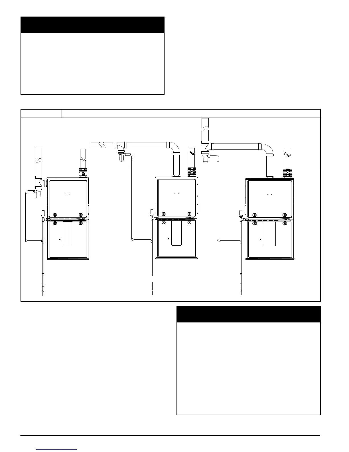
OPTIONAL CONFIGURATION FOR COMBUSTION AIR
INLET PIPE
In applications where there is a risk of excessive moisture
entering the combustion air inlet pipe, a moisture trap may be
added to the inlet pipe to help prevent moisture from entering
the furnace from the combustion air inlet pipe. See
Figure 49.
When sizing venting systems, the equivalent length of the
optional moisture trap (15 feet/5 M) must be taken into ac-
count
Optional Combustion Air Inlet
Moisture Trap
As an option to prevent moisture from trickling into the furnace
vestibule, a trap can be installed in the intake air pipe near the
furnace. Connecting a drain line to the trap is optional as trace
amounts of moisture will evaporate into the intake air stream. If
the combustion air inlet is located near a moisture exhaust
duct, or there are other concerns of excessive moisture being
drawn into the combustion air inlet, it is encouraged to connect
a drain line to the trap.
The trap can be constructed from a running tee of the same
diameter of the intake air pipe with EITHER a removable cap
attached to a 6-inch long pipe connected to the tee or the
External vent Trap Kit to help prevent contaminants from
entering the furnace. See Figure 49.
Figure 49 Optional Combustion Air Inlet Moisture Trap
Representative drawing only, some models may vary in appearance.
TO CODE−APPROVED DRAIN OR CONDENSATE PUMP
L12F028
The External Vent Trap Kit accessory may be used as a trap for
the combustion air inlet pipe if a large amount of moisture must
be removed. The drain line may be connected to the same
drain as the furnace condensate and the evaporator coil
condensate line ONLY if the inlet air trap drain and the
evaporator coil drain empty into an open segment of pipe
above the drain, See Figure 12. When using the External Vent
Trap Kit, refer to those instructions for proper drain
connections.
The tee may also be connected to the intake air pipe on the
side of the casing. See Figure 49.
In any configuration, it will be necessary to add the equivalent
length of the tee (15 feet/5 M) to the Total Equivalent Vent
Length of the venting system.
NOTICE
ADDITIONAL INFORMATION FOR POLYPROPYLENE
VENTING SYSTEMS
Polypropylene venting systems include flexible vent pipe.
These flexible vent pipes have a different equivalent vent
length than straight sections of PVC/ABS DWV vent pipe. Be
sure to make the appropriate deductions from the Maximum
Equivalent Vent Length (MEVL), or additions to the Total
Equivalent Vent Length (TEVL), when applying flexible vent
pipes in polypropylene venting systems. See the polypropyl-
ene vent system manufacturer’s installation instructions for
details.
When using metric-sized venting systems, use these equival-
encies for obtaining the proper MEVL from the Tables:
Use 2” Vent Tables for 60mm (o.d.) vent systems
Use 3” Vent Tables for 80mm (o.d.) vent systems
Use 4” Vent Tables for 100mm (o.d.) vent systems