Figure16
Formed Rubber Drain Grommet
INSTALL CLAMPS ON DRAIN ELBOW
ATTACH DRAIN ELBOW TO CONDENSATE
DRAIN TRAP }/
PULL DRAIN STUB
THROUGH CASING,
/
/
/
/
/
/
\
/
\
/
OPEN SPRING CLAMP
INSERT FACTORY-SUPPLIED 1/2-1N. CPVC
TO 3/4-1N. PVC ADAPTER OR 1/2-1N. CPVC PIPE
*CLAMP MAY BE LOCATED ON OUTSIDE OF DRAIN ELBOW
RIGHT SIDE DRAIN INSTALLATION
L12F022
Figure 17 _Horizontal Drain Trap Grommet
4_ _' QRemove knockout
_a _tgr _mmn_t:Jote
trap.
Al1348
INSTALLATION
This furnace is certified to leak 2% or less of nominal air con-
ditioning CFM delivered when pressurized to 1-inch water
column (250 Pa) with all present air inlets (including bottom
closure in upflow and horizontal applications), air outlets, and
plumbing and electrical ports sealed.
UPFLOW INSTALLATION
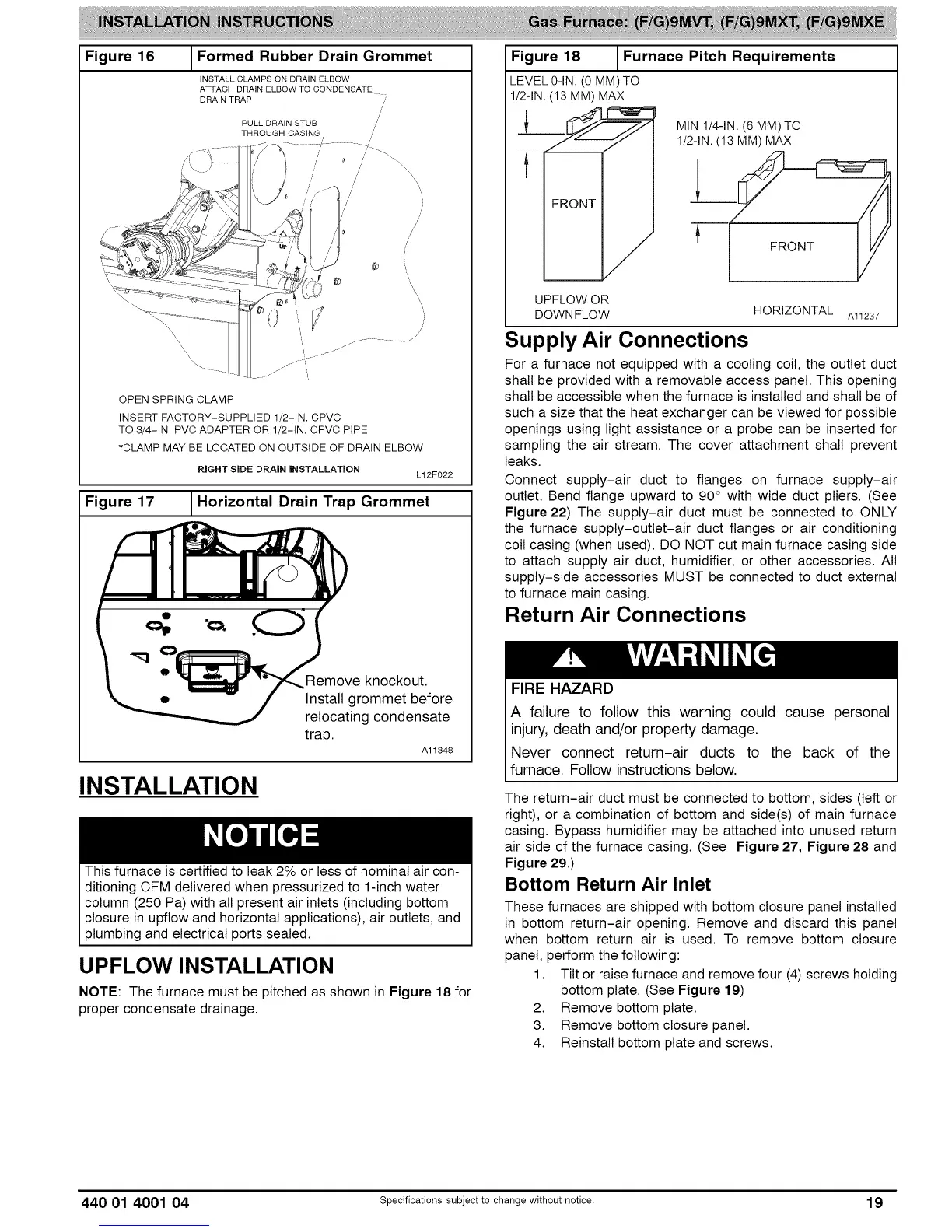
NOTE: The furnace must be pitched as shown in Figure 18 for
proper condensate drainage.
Figure 18 1Furnace Pitch Requirements
LEVEL 0-IN. (0 MM) TO
1/2-iN. (13 MM) MAX
MIN1/4-1N.(6 MM)TO
l/2qN. (13 MM) MAX
UPFLOW OR
DOWNFLOW HORIZONTAL Al1237
Supply Air Connections
For a furnace not equipped with a cooling coil, the outlet duct
shall be provided with a removable access panel. This opening
shall be accessible when the furnace is installed and shall be of
such a size that the heat exchanger can be viewed for possible
openings using light assistance or a probe can be inserted for
sampling the air stream. The cover attachment shall prevent
leaks.
Connect supply-air duct to flanges on furnace supply-air
outlet. Bend flange upward to 90° with wide duct pliers. (See
Figure 22) The supply-air duct must be connected to ONLY
the furnace supply-outlet-air duct flanges or air conditioning
coil casing (when used). DO NOT cut main furnace casing side
to attach supply air duct, humidifier, or other accessories. All
supply-side accessories MUST be connected to duct external
to furnace main casing.
Return Air Connections
FIRE HAZARD
A failure to follow this warning could cause personal
injury, death and/or property damage.
Never connect return-air ducts to the back of the
furnace. Fo ow nstruct ons be ow.
The return-air duct must be connected to bottom, sides (left or
right), or a combination of bottom and side(s) of main furnace
casing. Bypass humidifier may be attached into unused return
air side of the furnace casing. (See Figure 27, Figure 28 and
Figure 29.)
Bottom Return Air Inlet
These furnaces are shipped with bottom closure panel installed
in bottom return-air opening. Remove and discard this panel
when bottom return air is used. To remove bottom closure
panel, perform the following:
1. Tilt or raise furnace and remove four (4) screws holding
bottom plate. (See Figure 19)
2. Remove bottom plate.
3. Remove bottom closure panel.
4. Reinstall bottom plate and screws.
440 01 4001 04 specificationssubjectto change without notice. 19