Table 4 Minimum Space Volumes for 100% Combustion, Ventilation and Dilution Air from Outdoors
OTHER THAN FAN-ASSISTED TOTAL FAN-ASSISTED TOTAL
(1,000'S BTUH GAS INPUT RATE) (1,000'S BTUH GAS INPUT RATE)
30 40 50 40 60 80 1 O0 120 140
AOH Space Volume Ft 3 (M 3)
1,050 1,400 1,750 1,400 1,500 2,000 2,500 3,000 3,500
0.60 (29.7) (39.6) (49.5) (39.6) (42.5) (56.6) (70.8) (84.9) (99.1)
1,260 1,680 2,1 O0 1,680 1,800 2,400 3,000 3,600 4,200
0.50 (35.6) (47.5) (59.4) (47.5) (51.0) (67.9) (84.9) (101.9) (118.9)
1,575 2,1 O0 2,625 2,1 O0 2,250 3,000 3,750 4,500 5,250
0.40 (44.5) (59.4) (74.3) (59.4) (63.7) (84.9) (106.1 ) (127.3) (148.6)
2,1 O0 2,800 3,500 2,800 3,000 4,000 5,000 6,000 7,000
0.30 (59.4) (79.2) (99.1) (79.2) (84.9) (113.2) (141.5) (169.8) (198.1 )
3,150 4,200 5,250 4,200 4,500 6,000 7,500 9,000 10,500
0.20 (89.1) (118.9) (148.6) (118.9) (127.3) (169.8) (212.2) (254.6) (297.1)
6,300 8,400 10,500 8,400 9,000 12,000 15,000 18,000 21,000
0,10 (178.0) (237.8) (297.3) (237.8) (254.6) (339.5) (424.4) (509.2) (594.1)
0,00 NP NP NP NP NP NP NP NP NP
NP = Not Permitted
CONDENSATE TRAP
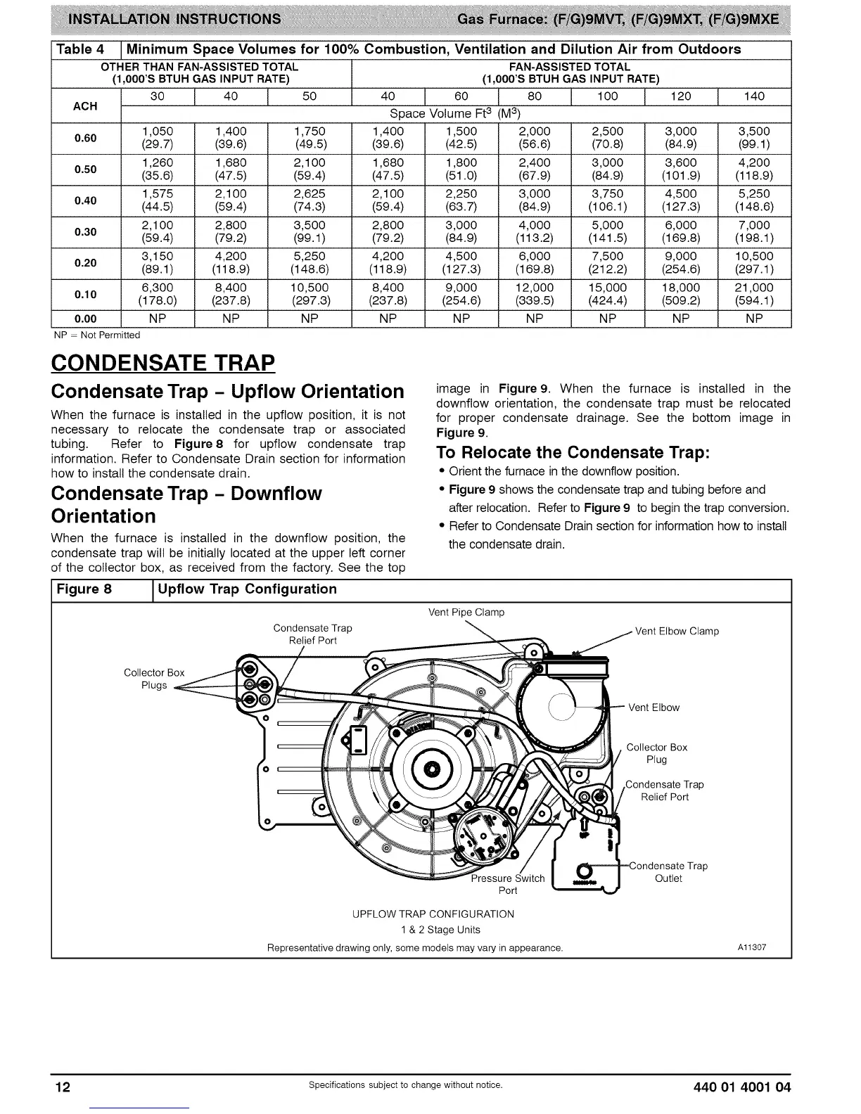
Condensate Trap - Upflow Orientation
When the furnace is installed in the upflow position, it is not
necessary to relocate the condensate trap or associated
tubing. Refer to Figure8 for upflow condensate trap
information. Refer to Condensate Drain section for information
how to install the condensate drain.
Condensate Trap - Downflow
Orientation
When the furnace is installed in the downflow position, the
condensate trap will be initially located at the upper left corner
of the collector box, as received from the factory. See the top
Figure 8 _Upflow Trap Configuration
I
Condensate Trap
Relief Port
image in Figure9. When the furnace is installed in the
downflow orientation, the condensate trap must be relocated
for proper condensate drainage. See the bottom image in
Figure 9.
To Relocate the Condensate Trap:
• Orient the furnace in the downflow position.
• Figure 9 shows the condensate trap and tubing before and
after relocation. Refer to Figure 9 to begin the trap conversion.
• Refer to Condensate Drain section for information how to install
the condensate drain.
Vent Pipe Clamp
Vent Elbow Clamp
Collector Box
Plugs
Vent Elbow
Pressure Switch
Port
UPFLOW TRAP CONFIGURATION
1 & 2 Stage Units
Representative drawing only, some models may vary in appearance.
Collector Box
Plug
Condensate Trap
Relief Port
Outlet
Al1307
12 specificationssubjectto change without notice. 440 01 4001 04