3. Remove the knock-out for the condensate trap in the
side of the casing.
4. Install the drain trap grommet in the casing, if required for
direct-vent applications. If necessary, remove the trap,
install the grommet and re-install the trap.
5. Remove the pre-formed rubber drain elbow and two
spring clamps from the loose parts bag.
6. Connect the full or modified elbow and/or grommet to the
outlet of the condensate trap with one spring clamp.
Avoid misalignment of the drain pipe which may cause
kinks in the elbow or grommet.
7. The remaining drain line can be constructed from field
supplied 1/2-in. CPVC or 3/4-in. PVC pipe, in
compliance with local building codes. A factory-supplied
1/2-in. CPVC to 3/4-in. PVC adapter is supplied in the
loose parts bag for use as required.
8. Install the adapter or connect the 1/2-in. CPVC pipe by
sliding a spring clamp over the open end of the elbow or
grommet on the outside the furnace casing.
9. Open the spring clamp and insert the long end of the
adapter or the 1/2-in. CPVC pipe into the outlet stub on
the drain elbow.
10. Connect additional condensate piping to a
code-approved drain, or to a condensate pump
approved for use with acidic furnace condensate and
compatible with mineral and vegetable oils, such as
canola oil.
Allow at least 1/4-in. per foot (20 mm per meter) of slope down
and away from the furnace in horizontal sections of drain line.
Figure 13 I Knockout Removal
i
o
J
,5.°¢
/"1
L12F019
CUT HAZARD
Failure to follow this caution may result in personal
injury.
Sheet metal parts may have sharp edges or burrs. Use
care and wear appropriate protective clothing, safety
glasses and gloves when handling parts, and servicing
furnaces.
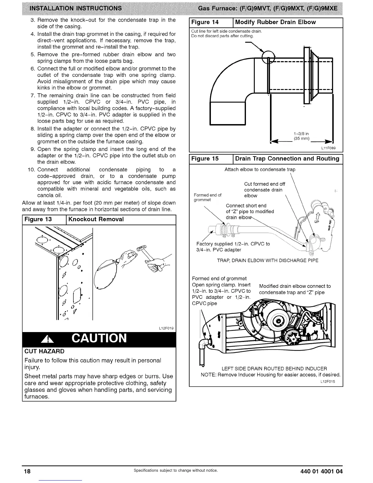
Figure 14
Cut line for left side condensate drain.
Do not discard parts after cutting,
Modify Rubber Drain Elbow
&
1-3/8 in
(35 mm)
L11F089
Figure 15 IDrain Trap Connection and Routing
Attach elbow to condensate trap
Cut formed end off
condensate drain
Formed end of elbow
grommet
Oonnect short end
of "Z" pipe to modified
drain
, i
Factory supplied 1/2-in. CPVC to
3/4-in. PVC adapter
TRAP, DRAIN ELBOW WITH DISCHARGE PIPE
Formed end of grommet
Open spring clamp. Insert
1/2-in. to 3/4-in, CPVC to
PVC adapter or 1/2-in,
CPVC pipe
Modified drain elbow connect to
condensate trap and "Z" pipe
LEFT SIDE DRAINROUTED BEHIND INDUCER
NOTE: Remove Inducer Housing for easier access, if desired.
Lt2F015
18 Specificationssubjectto change without notice. 440 01 4001 04