Heating and Cooling Application Two-Stage Wiring Diagram with Single-Stage Thermostat
.... FIELD 24-VOLT WIRING
.... FIELD 115-, 208/230-, 460-VOLT WIRING
-- FACTORY 24-VOLT WIRING
FACTORY 115-VOLT WIRING
115-VOLT FIELD-
SUPPLIED
FUSED
DISCONNECT
NOTE 2
@/THERMOSTAT
FIVE_ (_ (_ (_ (_) 1 1-STAGE
_ /TERMINALS
WIRE__.__ : : ..........................
BLOWER THREE_WIRE_ T --T
DOOR_ REATING-"__ ' '
SWITCH _ ONLY __
.P,_ oV_=c O
JUNCTION
BOX
NO
T
RO
O
L®
@-
24-VOLT
TERMINAL
BLOCK
I
i
i
i
J
i-
I
J
NOTE1
P
I
I
FURNACE
FELD-SUPPLIED
FUSED DISCONNECT
i_iiii/!!iiiii!iiiiiii!i[iiii!iiiiii;ii_;iiiii;i
I
a
_IP-----_I_, e-41-4
i J I=,
L 9_---------=bJ I1/
[tT208/230 OR
460-VOLT
HREE
HASE
1_]_ _]_l =7208/230-
[ : t_VO LT
[SINGLE
CONDENSING
UNIT
NOTES: 1. Connect Y/Y2-terminal as shown for proper operation.
2. Some thermostats require a "C" terminal connection as shown.
3. If any of the original wire, as supplied, must be replaced, use
same type or equivalent wire.
J-Box Installation
FIRE OR ELECTRICAL SHOCK HAZARD
Failure to follow this warning could result in personal
injury, death, or property damage.
If field-supplied manual disconnect switch is to be
mounted on furnace casing side, select a location where
a drill or fastener cannot damage electrical or gas
components.
The J-Box is used when field line voltage electrical connections
are made to the furnace wiring harness inside the furnace
casing. The J-Box is not required if a field-supplied electrical
box is attached to the outside of the furnace casing and the box
is grounded to the green ground wire of the main wiring
harness and the earth ground of the field electrical supply.
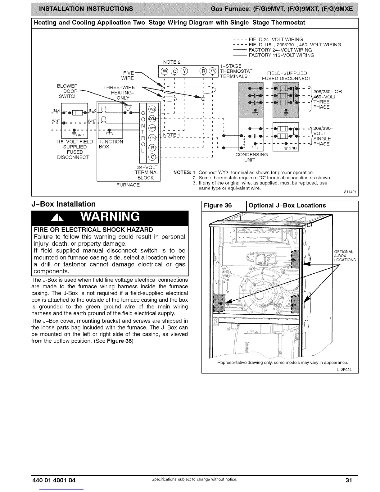
The J-Box cover, mounting bracket and screws are shipped in
the loose parts bag included with the furnace. The J-Box can
be mounted on the left or right side of the casing, as viewed
from the upflow position. (See Figure 36)
Figure 36 Optional J-Box Locations
J
J
Al1401
OPTIONAL
J-BOX
LOCATIONS
7
Representative drawing only, some models may vary in appearance.
L12F024
440 01 4001 04 Specifications subject to change without notice. 31