Figure 9
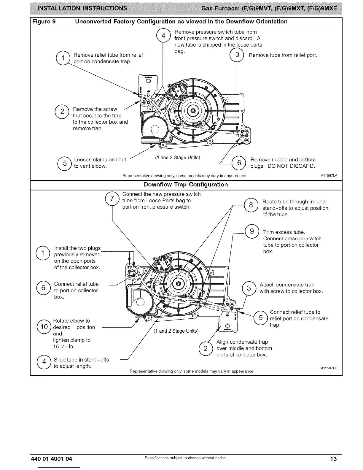
Unconverted Factory Configuration as viewed in the Downflow Orientation
Remove pressure switch tube from
front pressure switch and discard. A
new tube is shipped in the loose parts
tief
(_ emovethe screw /
that secures the trap
to the collector box and
remove trap.
Remove tube from relief port.
i
(_ Loosen clamp on inlet (1 and 2 Stage Units) Remove middle and bottom
to vent elbow, plugs. DO NOT DISCARD.
Representative drawing only, some models may vary in appearance. A11587LA
Downflow Trap Configuration
(_ nstall the two plugs
previously removed
on the open ports
of the collector box.
(_) Connect relief tube
to port on collector
box.
(_ Rotate elbow to
desired position
and
tighten clamp to
15 lb.-in.
(_ Slide tube in stand-offs
to adjust length.
?
Connect the new pressure switch
tube from Loose Parts bag to _ Route tube through inducer
port on front pressure switch. _ stand-offs to adjust position
/ of the tube.
/ / r___-k N ) Trim excess tube.
/ / / X"-J Connect Pressure switch
/ / / tube to port on collector
.,,,_ _,, ' / t box.
I__i _ (/_ Attach condensate trap
_,,\VV___ _,_ I,_ If====/II \ _ ) with screw to collector box.
_ ___----- _ relief port on condensate
/ trap.
(1 and 2 Stage Units)
/_= Align condensate trap
ports of collector box.
Representative drawing only, some models may vary in appearance.
A11587LB
440 01 4001 04 specificationssubjectto change without notice. 13