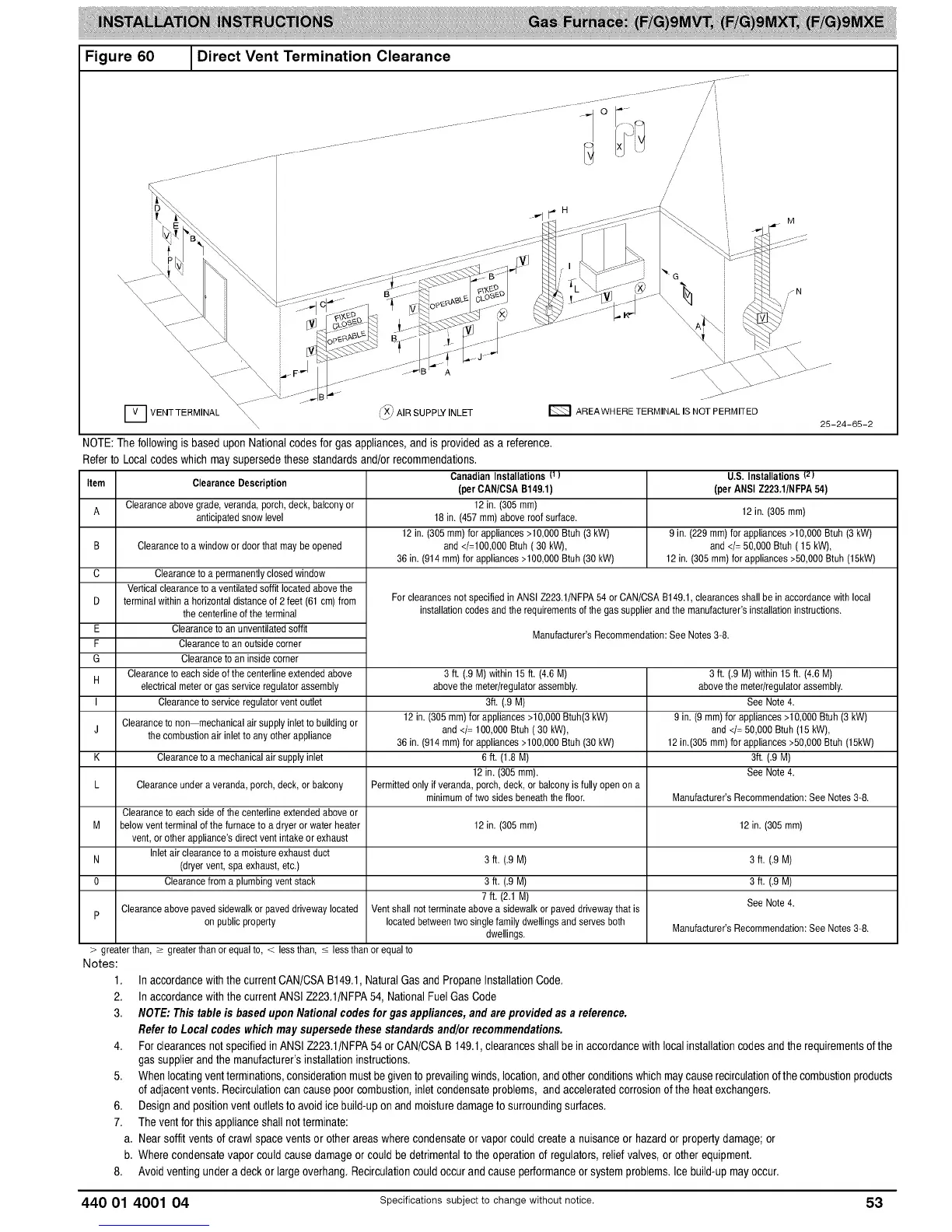
Figure 60
/
H
G
AREAWHERE TERMINAL IS NOT PERMITED
25-24-65-2
[] VEHTTERMINAL \\\X _/_ AIRSUPPLYINLET
NOTE: The following is based upon National codes for gas appliances, and is provided as a reference.
Refer to Local codes which may supersede these standards and/or recommendations.
Item Clearance Description
A Clearanceabove grade,veranda, porch,deck,balcony or
anticipatedsnowlevel 12 in. (305 ram)
9in. (229mm)for appliances >10,000Btuh (3 kW)
Clearanceto a window or doorthat maybe opened and</= 50,000 Btuh( 15 kW),
12 in. (305 ram)for appliances>50,000 Btuh (15kW)
B
C Clearanceto a permanentlyclosedwindow
Verticalclearance to a ventilated soffitlocated abovethe
D terminalwithin a horizontaldistanceof 2 feet (61 cm)from
the centerlineof the terminal
E Clearanceto an unventilatedsoffit
F Clearanceto an outsidecorner
G Clearanceto an inside corner
Clearanceto eachside of the centerlineextendedabove
H
electrical meteror gas serviceregulator assembly
I Clearanceto serviceregulatorventoutlet
Clearanceto non mechanicalair supplyinlet to buildingor
thecombustionair inletto any other appliance
Clearanceto a mechanicalair supply inlet
CanadianInstallations {1)
(perCAN/CSA B149.1)
12 in. (305 ram)
18 in. (457 ram)aboveroof surface.
12 in. (305 mm) for appliances>10,000Btuh (3 kW)
and</=100,000Btuh ( 30 kW),
36 in. (914 mm) for appliances>100,000Btuh (30 kW)
U.S. Installations Iz)
(perANSI Z223.1/NFPA54)
Forclearancesnot specifiedin ANSI Z223.1/NFPA54 or CAN/CSAB149.1,clearances shallbe in accordancewith local
installationcodes andthe requirements of the gas supplierand the manufacturer'sinstallationinstructions.
Manufacturer'sRecommendation:See Notes3-8.
3 ft. (.9 M)within15 ft. (4.6 M) 3 ft. (.9 M)within 15 ft. (4.6 M)
abovethe meter/regulatorassembly, abovethe meter/regulatorassembly.
3ft. (.9 M) See Note4.
12 in. (305 mm) forappliances >10,000Btuh(3 kW) 9 in. (9 ram)for appliances>10,000 Btuh (3kW)
J and</= 100,000 Btuh ( 30 kW), and</= 50,000 Btuh(15 kW),
36 in. (914 mm) for appliances>100,000Btuh (30 kW) 12in.(305 ram)for appliances>50,000 Btuh (15kW)
K 6 ft. (1.8 M) 3ft. (.9 M)
12 in. (305 mm). See Note4.
L Clearanceunder averanda,porch, deck,or balcony Permittedonly ifveranda, porch,deck, or balconyis fully openon a
minimumof two sidesbeneaththe floor. Manufacturer'sRecommendation:See Notes3-8.
Clearanceto eachsideof the centerline extendedaboveor
M belowvent terminalof the furnaceto a dryer or water heater 12 in. (305 ram) 12 in. (305ram)
vent, orother appliance's directvent intake or exhaust
Inletair clearanceto a moistureexhaust duct
N (dryer vent, spa exhaust, etc.) 3 ft. (.9 M) 3 ft. (.9 M)
0 Clearancefroma plumbingvent stack 3 ft. (.9 M) 3 ft. (.9 M)
7 ft. (2.1 M) See Note4.
Clearanceabovepaved sidewalkor paveddrivewaylocated Vent shallnot terminateabove a sidewalk orpaved drivewaythat is
P
on public property locatedbetweentwo singlefamily dwellingsand servesboth Manufacturer'sRecommendation:See Notes3-8.
dwellings.
> greaterthan, > greater than or equalto, < lessthan, < less than or equalto
Notes:
1.
2.
3.
Inaccordancewiththe current CAN/CSAB149,1,NaturalGas and PropaneInstallationCode,
Inaccordancewiththe current ANSIZ223,1/NFPA54, NationalFuelGas Code
NOTE: Thistable is based uponNationalcodesfor gasappliances,and areprovidedas a reference.
Referto Loca/codes whichmaysupersedethesestandardsand/orrecommendations.
4. Forclearancesnot specifiedinANSI Z223,1/NFPA54 orCAN/CSAB 149,1,clearancesshallbe in accordancewith localinstallationcodesandthe requirementsof the
gassupplierandthe manufacturer'sinstallationinstructions,
5. Whenlocatingventterminations,considerationmustbegiventoprevailingwinds,location,and otherconditionswhichmaycauserecirculationofthe combustionproducts
ofadjacentvents, Recirculationcancause poorcombustion,inletcondensateproblems, and acceleratedcorrosionofthe heatexchangers.
6. Designand positionventoutletsto avoid ice build-upon and moisturedamageto surroundingsurfaces,
7. The ventfor thisapplianceshallnotterminate:
a, Nearsoffit vents of crawl spacevents or otherareas wherecondensateor vaporcould create a nuisanceor hazardor properlydamage;or
b, Where condensatevapor couldcause damageor couldbe detrimentalto the operationof regulators,reliefvalves,or otherequipment,
8. Avoid ventingunderadeck or largeoverhang,Recirculationcouldoccurand cause performanceor systemproblems.Ice build-upmayoccur.
440 O1 4OO1 04 Specifications subject to change without notice. 53