ELECTRICAL SHOCK or UNIT DAMAGE HAZARD
Failure to follow this warning could result in personal injury,
death, and/or property damage.
Turn OFF electric power at fuse box or service panel before
making any electrical connections and ensure a proper
ground connection is made before connecting line voltage.
ELECTRICAL SHOCK HAZARD
Failure to follow this warning could result in personal injury
or death.
Turn OFF the main (remote) disconnect device before
working on incoming (field) wiring. Incoming (field) wiring on
the line side of the disconnect found in the modular blower
unit remains live, even when the pull-out is removed. Service
and maintenance to incoming (field) wiring cannot be
performed until the main disconnect switch (remote to the
unit) is turned off.
MF units installed without electric heat require the use of a factory-
authorized No Heat Kit (accessory part number EHIA00KN 10). This
kit provides the electrical connections necessary to supply the unit
with 208/230V power when electric heat is not present.
For units without electric heat:
1. Locate adapter and filler plates with screws inside package. If
necessary, adjust plates to allow for installation of No Heat Kit
required inside cabinet. Refer to Figure 7,
2. Secure No Heat Kit accessory with four (4) screws.
3. Connect the 9-pin plug from No Heat Kit wiring into the
receptacle that attaches to fan control board.
4. Connect ground wire to unit ground lug.
5. Connect 208/230V power lead from field disconnect to No Heat
Kit.
Heater Installation
For units with electric heat, see Electric
Instructions and blower airflow requirements.
NOTE: Transformer is factory-wired for 230V operation. For 208V
applications the transformer must be rewired to the 208V tap. Refer
to unit wiring label.
GROUNDING CONNECTION
Use a copper conductor(s) from the ground lug on the No Heat Kit
or ground lugs on the electric heater to a grounded connection in
the electric service panel or a properly installed grounding rod.
Low Voltage Control Connections
Wire low-voltage in accordance with wiring label on the blower (also
refer to Figures 8 - 12. Use 18 AWG color-coded, insulated (35_C
minimum) wire to make the low-voltage connections between:
thermostat, indoor equipment, and outdoor equipment. If thermostat
is located more than 100 feet (31m) from the unit (as measured
along the low voltage wire), use 16 AWG color-coded, insulated
(35_C minimum) wire. All wiring must be NEC Class 1 and must be
separated from incoming power leads. Refer to outdoor unit wiring
instructions for additional wiring recommendations.
Field supplied low-voltage wiring should be field connected inside
control splice box area (secure with wire nuts), and strain relief
bushing or rubber grommet to seal cabinet opening.
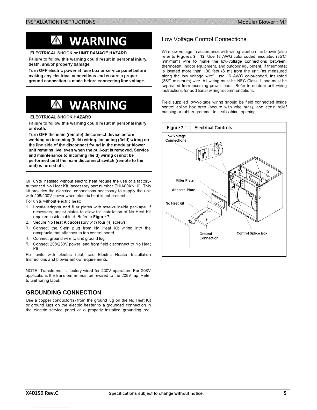
Figure7 J Electrical Controls
LowVoltage
Connections
\,
FillerPlate
Adapter Plate
\
No Heat Kit _\
Ground
Connection
Control Splice Box
X40159 Rev.C Specifications subject to change without notice. 5
 Loading...