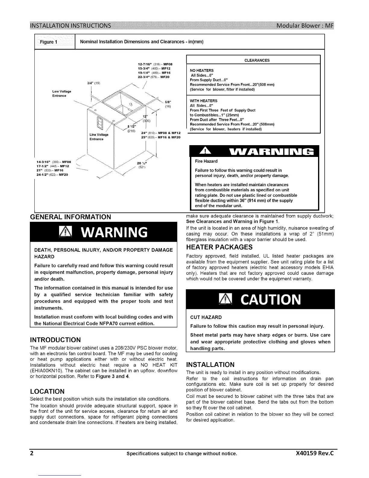
Figure i Nominal Installation Dimensions and Clearances-in(ram)
Low Voltage
Entrance
14-3/16" (360/- MFO8
17.112" (445/- MF12
21" (533/- MF16
24-1/2" (622/- MF20
314" (19)
12-7/16" (316/- MF08
15-3/4" (400)- MF12
19-1/4" (489)- MF16
22-3/4" (578)- MF20
Line Voltage | 24" (610)- MFO8 & MF12
Entrance l 25" (635)- MF16 & MF20
CLEARANCES
NO HEATERS
All Sides...0"
From Supply Duct_.0"
Recommended Service From Front_.20"(508 mm)
(Service for blower, filter if installed)
WITH HEATERS
All Sides...O"
From First Three Feet of Supply Duct
to Combustibles...1" (25ram)
From Duct after Three Feet...0"
Recommended Service From Front...20" (508mm)
(Service for blower, heaters if installed)
Fire Hazard
Failure to follow this warning could result in
personal injury, death, and/or property damage.
When heaters are installed maintain clearances
from combustible materials as specified on unit
rating plate. Do not use plastic lined or combustible
flexible ducting within 36" (914 mm) of the supply
end of the modular unit.
GENERAL INFORMATION
DEATH, PERSONAL INJURY, AND/OR PROPERTY DAMAGE
HAZARD
Failure to carefully read and follow this warning could result
in equipment malfunction, property damage, personal injury
and/or death.
The information contained in this manual is intended for use
by a qualified service technician familiar with safety
procedures and equipped with the proper tools and test
instruments.
Installation must conform with local building codes and with
the National Electrical Code NFPA70 current edition.
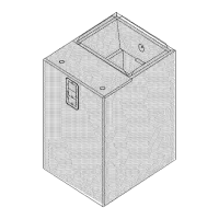
INTRODUCTION
The MF modular blower cabinet uses a 208/230V PSC blower motor,
with an electronic fan control board. The MF may be used for cooling
or heat pump applications either with or without electric heat.
Installations without electric heat require a NO HEAT KIT
(EHIA00KN10). The cabinet can be installed in an upflow, downflow
or horizontal position. Refer to Figure 3 and 4.
LOCATION
Select the best position which suits the installation site conditions.
The location should provide adequate structural support, space in
the front of the unit for service access, clearance for return air and
supply duct connections, space for refrigerant piping connections
and condensate drain line connections. If heaters are being installed,
make sure adequate clearance is maintained from supply ductwork;
See Clearances and Warning in Figure 1.
If the unit is located in an area of high humidity, nuisance sweating of
casing may occur. On these installations a wrap of 2" (51mm)
fiberglass insulation with a vapor barrier should be used.
HEATER PACKAGES
Factory approved, field installed, UL listed heater packages are
available from the equipment supplier. See unit rating plate for a list
of factory approved heaters (electric heat accessory models EHIA
only). Heaters that are not factory approved could cause damage
which would not be covered under the equipment warranty.
CUT HAZARD
Failure to follow this caution may result in personal injury.
Sheet metal parts may have sharp edges or burrs. Use care
and wear appropriate protective clothing and gloves when
handling parts.
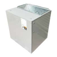
INSTALLATION
The unit is ready to install in any position without modifications.
Refer to the coil instructions for information on drain pan
configurations etc. Make sure coil is set up properly for desired
position of blower cabinet.
Coil must be secured to blower cabinet with the three tabs that are
part of the blower cabinet base. Bend the tabs out from the bottom
so they fit over the coil cabinet.
Position coil cabinet in relation to the blower so they will be correct
for desired application.
2 Specifications subject to change without notice. X40159 Rev.C
 Loading...