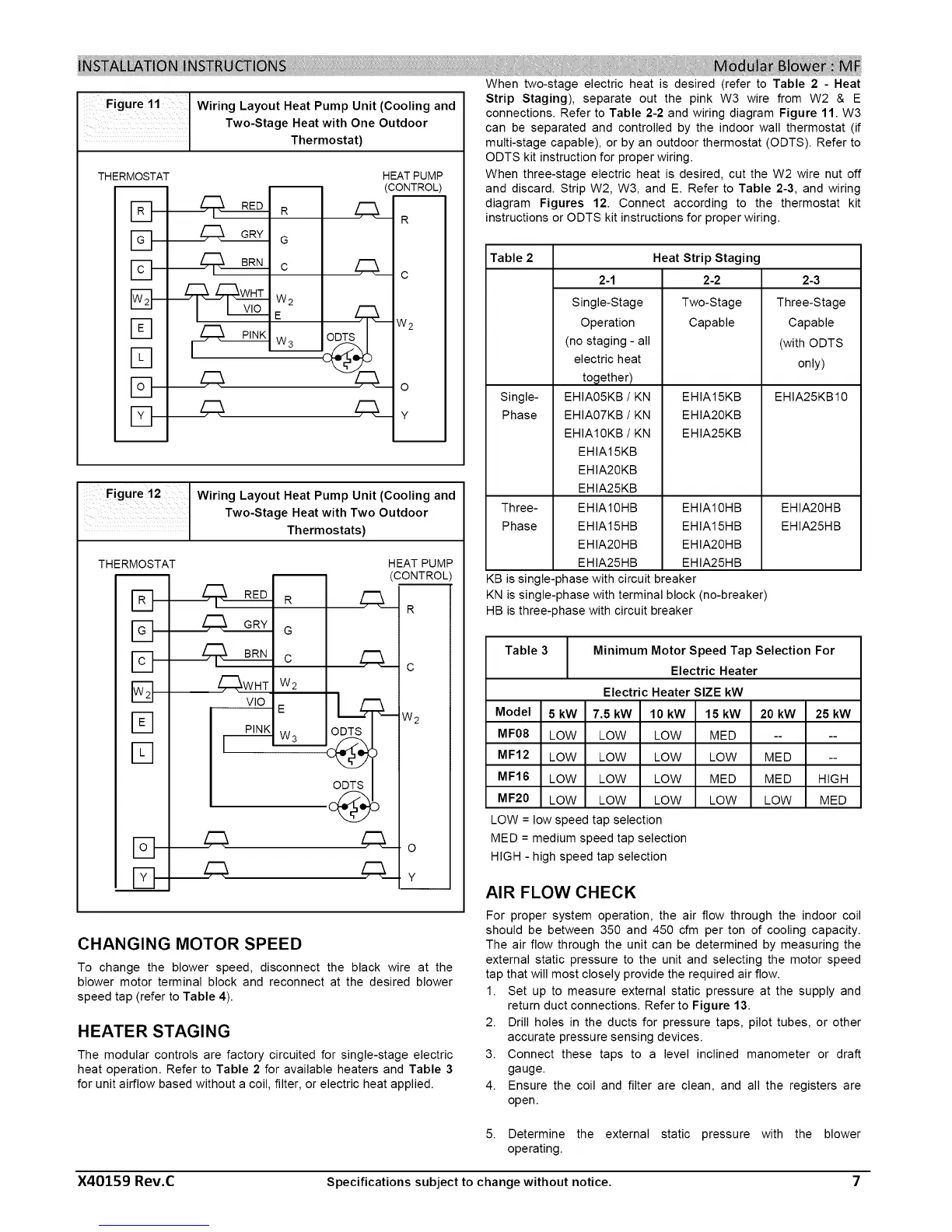
Wiring Layout Heat Pump Unit (Cooling and
Two-Stage Heat with One Outdoor
Thermostat)
THERMOSTAT
m
D-
J3-
D-
E3-
[-q
Fq
E]-
D-
m
R
G
c
W2
E
W3- ODTS
z;:5._
HEATPUMP
(CONTROL)
R
c
w2
o
Y
- .-t.igure 1z I Wiring Layout Heat Pump Unit (Cooling and
1
Two-Stage Heat with Two Outdoor
Thermostats)
THERMOSTAT
m
D-
%
Fq
_WHT
VlO
PINK
m
R
G
C
W2
E
w3.....2.__
HEAT PUMP
(CONTROL)
4Q_ R
L __c
o Lw2
ODTS
£___y
CHANGING MOTOR SPEED
To change the blower speed, disconnect the black wire at the
blower motor terminal block and reconnect at the desired blower
speed tap (refer to Table 4).
HEATER STAGING
The modular controls are factory circuited for single-stage electric
heat operation. Refer to Table 2 for available heaters and Table 3
for unit airflow based without a coil, filter, or electric heat applied.
When two-stage electric heat is desired (refer to Table 2 - Heat
Strip Staging), separate out the pink W3 wire from W2 & E
connections. Refer to Table 2-2 and wiring diagram Figure 11. W3
can be separated and controlled by the indoor wall thermostat (if
multi-stage capable), or by an outdoor thermostat (ODTS). Refer to
ODTS kit instruction for proper wiring.
When three-stage electric heat is desired, cut the W2 wire nut off
and discard. Strip W2, W3, and E. Refer to Table 2-3, and wiring
diagram Figures 12. Connect according to the thermostat kit
instructions or ODTS kit instructions for proper wiring.
Table 2 Heat Strip Staging
2-1 2-2
Single-Stage Two-Stage
Operation Capable
(no staging - all
electric heat
Single- EHIA05KB / KN EHIA15KB
Phase EHIA07KB / KN EHIA20KB
EHIA10KB / KN EHIA25KB
EHIA15KB
EHIA20KB
EHIA25KB
Three- EHIA10HB EHIA10HB
Phase EHIA15HB EHIA15HB
EHIA20HB EHIA20HB
EHIA25HB EHIA25HB
KB is single-phase with circuit breaker
KN is single-phase with terminal block (no-breaker)
HB is three-phase with circuit breaker
2-3
Three-Stage
Capable
(with ODTS
only)
EHIA25KB10
EHIA20HB
EHIA25HB
Table 3 Minimum Motor Speed Tap Selection For
Electric Heater
Electric Heater SIZE kW
Model 5 kW 7.5 kW 10 kW 15 kW 20 kW 25 kW
MF08 LOW LOW LOW MED ....
MF12 LOW LOW LOW LOW MED --
MF16 LOW LOW LOW MED MED HIGH
MF20 LOW LOW LOW LOW LOW MED
LOW = low speed tap selection
MED = medium speed tap selection
HIGH - high speed tap selection
AIR FLOW CHECK
For proper system operation, the air flow through the indoor coil
should be between 350 and 450 cfm per ton of cooling capacity.
The air flow through the unit can be determined by measuring the
external static pressure to the unit and selecting the motor speed
tap that will most closely provide the required air flow.
1. Set up to measure external static pressure at the supply and
return duct connections. Refer to Figure 13.
2. Drill holes in the ducts for pressure taps, pilot tubes, or other
accurate pressure sensing devices.
3. Connect these taps to a level inclined manometer or draft
gauge.
4. Ensure the coil and filter are clean, and all the registers are
open.
5. Determine the external static pressure with the blower
operating.
X40159 Rev.C Specifications subject to change without notice. 7
 Loading...