7.
8.
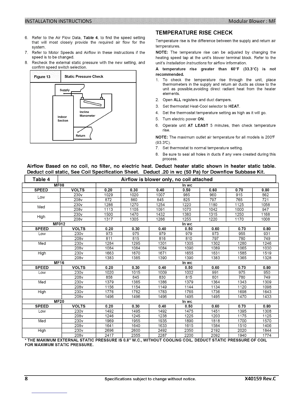
Refer to the Air Flow Data, Table 4, to find the speed setting
that will most closely provide the required air flow for the
system.
Refer to Motor Speeds and Airflow in these instructions if the
speed is to be changed.
Recheck the external static pressure with the new setting, and
confirm speed switch selection.
StaticPressoroCheck
TEMPERATURE RISE CHECK
Temperature rise is the difference between the supply and return air
temperatures.
NOTE: The temperature rise can be adjusted by changing the
heating speed tap at the unit's blower terminal block. Refer to the
unit's Installation Instructions for airflow information.
A temperature rise greater than 60°F (33,3°C) is not
recommended.
1. To check the temperature rise through the unit, place
thermometers in the supply and return air ducts as close to the
unit as possible,avoiding direct radiant heat from the heater
elements.
2. Open ALL registers and duct dampers.
3. Set thermostat Heat-Cool selector to HEAT.
4. Set the thermostat temperature setting as high as it will go.
5. Turn electric power ON.
6. Operate unit AT LEAST 5 minutes, then check temperature
rise.
NOTE: The maximum outlet air temperature for all models is 200°F
(93.3°C).
7. Set thermostat to normal temperature setting.
8. Be sure to seal all holes in ducts if any were created during this
process.
Airflow Based on no coil, no filter, no electric heat. Deduct heater static shown in heater static table.
Deduct coil static, See Coil Specification Sheet. Deduct .20 in wc (50 Pa) for Downflow Subbase Kit.
Table 4 Airflow is blower only, no coil attached
MF08 In wc
SPEED VOLTS 0.20 0.30 0.40 0.50 0.60 0.70 0.80
230v 1029 1020 1007 985 960 915 862
Low
208v 872 860 845 825 797 765 721
230v 1286 1270 1254 1220 1180 1125 1058
Med
208v 1113 1105 1091 1070 1042 1000 947
230v 1500 1470 1432 1380 1315 1250 1168
High 208v 1317 1305 1286 1255 1220 1170 1008
MF012 In wc
SPEED VOLTS 0.20 0.30 0.40 0.50 0.60 0.70 0.80
Low 230v 973 975 979 979 973 955 931
208v 811 815 816 810 797 780 749
Med 230v 1284 1295 1301 1305 1302 1280 1246
208v 1084 1084 1084 1090 1089 1065 1030
High 230v 1663 1670 1671 1655 1631 1585 1519
208v 1383 1385 1390 1390 1383 1365 1328
MF16 In wc
SPEED VOLTS 0.20 0.30 0.40 0.50 0.60 0.70 0.80
Low 230v 1020 1015 1009 1002 991 975 950
208v 858 845 830 815 801 780 749
Med 230v 1379 1385 1386 1379 1364 1343 1309
208v 1156 1154 1149 1144 1134 1120 1098
High 230v 1776 1782 1783 1765 1736 1698 1643
208v 1496 1496 1496 1495 1495 1470 1433
MF20 In wc
SPEED VOLTS 0.20 0.30 0.40 0.50
Low 230v 1492 1495 1492 1475
208v 1246 1245 1238 1225
Med 230v 1969 1955 1935 1890
208v 1641 1640 1633 1615
High 230v 2696 2600 2492 2350
208v 2417 2355 2287 2200
0.60 0.70 0.80
1451 1395 1308
1203 1175 1125
1818 1700 1570
1584 1510 1406
2192 2020 1844
2092 1940 1774
DEDUCT STATIC PRESSURE OF COIL
* THE MAXIMUM EXTERNAL STATIC PRESSURE IS 0.8" W.C., WITHOUT COOLING
FOR MAXIMUM STATIC PRESSURE.
COIL.
8 Specifications subject to change without notice. X40159 Rev.C
 Loading...