2. Usemetalstrappingorthreadedrodwithangleironsupports
undertheauxiliarydrainpantosuspendcabinet.Thesesupports
MUST run parallel with the length of the cabinet. Refer to Figure
5.
3. Ensure that there is adequate room to remove service and
access panels after installing supporting brackets.
4. Place field installed vibration isolators in auxiliary drain pan to
support cabinet.
DUCT CONNECTIONS
Supply Duct
Supply duct must be attached to the outside of flange on outlet end
of unit. Flexible connectors may be used if desired. Maintain
clearances from supply duct to combustibles when heaters are
installed. Refer to Figure 1 and unit rating plate.
Return Duct
Return duct should be attached to bottom of unit using sheet metal
screws or other fasteners.
FILTER INSTALLATION
Filters must be field supplied. A remote filter grille or other means
must be provided. Refer to ACCA Manual D for remote filter sizing.
Figure 5 Horizontal Installation
see Note
Below
, rnT
_ '\ / _ _ Refrigerant
....._ _\'_ \Lines
Vibration Field-Fabricated
DrainPan _-_-_
Isolators
Supports MUST run parallel with blower cabinet
NOTE: If increased structural strength is needed in the horizontal
position, use field supplied two connecting plates in place of the tabs
on the bottom of the blower.
ELECTRICAL CONNECTIONS
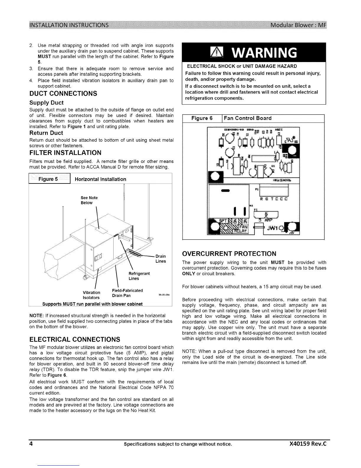
The MF modular blower utilizes an electronic fan control board which
has a low voltage circuit protective fuse (5 AMP), and pigtail
connections for thermostat hook up. The fan control also has a relay
for blower operation, and built in 90 second blower-off time delay
relay (TDR). To disable the TDR feature, snip the jumper wire JWI.
Refer to Figure 6.
All electrical work MUST conform with the requirements of local
codes and ordinances and the National Electrical Code NFPA 70
current edition.
The low voltage transformer and the fan control are standard on all
models and are prewired at the factory. Line voltage connections are
made to the heater accessory or the lugs on the No Heat Kit.
ELECTRICAL SHOCK or UNIT DAMAGE HAZARD
Failure to follow this warning could result in personal injury,
death, and/or property damage.
If a disconnect switch is to be mounted on unit, select a
location where drill and fasteners will not contact electrical
refrigeration components.
Figure 6
Fan Control Board
OVERCURRENTPROTECTION
The power supply wiring to the unit MUST be provided with
overcurrent protection. Governing codes may require this to be fuses
ONLY or circuit breakers.
For blower cabinets without heaters, a 15 amp circuit may be used.
Before proceeding with electrical connections, make certain that
supply voltage, frequency, phase, and circuit ampacity are as
specified on the unit rating plate. See unit wiring label for proper field
high and low voltage wiring. Make all electrical connections in
accordance with the NEC and any local codes or ordinances that
may apply. Use copper wire only. The unit must have a separate
branch electric circuit with a field-supplied disconnect switch located
within sight from and readily accessible from the unit.
NOTE: When a pull-out type disconnect is removed from the unit,
only the Load side of the circuit is de-energized. The Line side
remains live until the main (remote) disconnect is turned off.
4 Specifications subject to change without notice. X40159 Rev.C
 Loading...