8.2) Humidifier:
Terminals are provided to direct 115 volts @ 1.0 Amp maximum to the
transformer powering the humidifier. The humidifier will be energised
anytime the blower is operating on the "Heating Speed". Wire the 115-
volt power as indicated in figure #6.
8.3) Air conditioning:
An air conditioning coil may be installed on the supply air side only.
Also, notwithstanding the evaporator coil manufacturer's instructions,
a minimum of 6 inches clearance must be allowed between the bottom
of the coil drain pan, and the top of the heat exchanger. Wire the
thermostat and condensing unit contactor as indicated in figure #6.
8.4) Ductwork and Filter:
Installation:
Design and install air distribution system to comply with Air
Conditioning Contractors of America manuals or other approved
methods that conform to local codes and good trade practices.
When furnace supply ducts carry air outside furnace area, seal return
air duct to furnace casing and terminate duct outside furnace space.
Install air conditioning cooling coil (evaporator)on down.steam side (in
the supply air plenum) or furnace.
If separate evaporator and blower unit is used, install good sealing
dampers for air flow control. Cold air from the evaporator coil going
through the furnace could cause condensation and shorten furnace
life.
I CAUTION
Dampers (purchased locally) MUST be automatic.
Poison carbon monoxide gas hazard.
Do NOT draw return air from inside a closet or
utility room. Return air duct MUST be sealed to
furnace casing.
Failure to properly seal duct can result in death,
personal injury and/or property damage.
Poison carbon monoxide gas hazard.
Install evaporator coil on the supply side of the
furnace ducting.
Evaporator coil installed in return side ducting can
cause condensation to f_rm inside heat exchanger
resulting in heat exchanger failure. This could
result in death, personal injury and/or property
damage.
PART 2
OPERATION
1)
MANUAL OPERATION SWITCHES
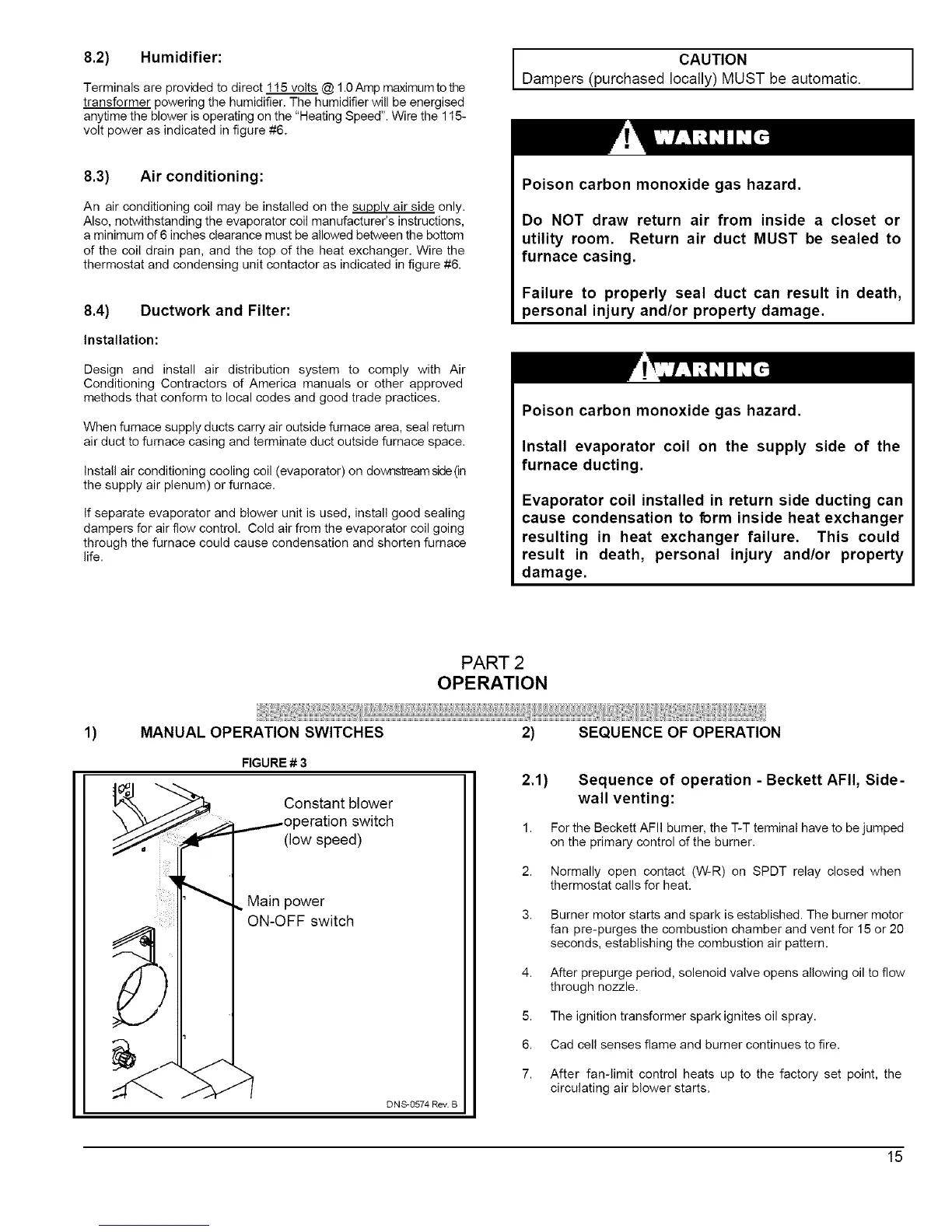
FIGURE # 3
Constant blower
3eration switch
(low speed)
Main power
ON-OFF switch
DNS-0574 Rev. B
2) SEQUENCE OF OPERATION
2.1) Sequence of operation - Beckett AFII, Side-
wall venting:
1. For the Beckett AFII burner, the T-T terminal have to be jumped
on the primary control of the burner.
2. Normally open contact (W-R) on SPDT relay closed when
thermostat calls for heat.
3. Burner motor starts and spark is established. The burner motor
fan pre-purges the combustion chamber and vent for 15 or 20
seconds, establishing the combustion air pattern.
4. After prepurge period, solenoid valve opens allowing oil to flow
through nozzle.
5. The ignition transformer spark ignites oil spray.
6. Cad cell senses flame and burner continues to fire.
7. After fan-limit control heats up to the factory set point, the
circulating air blower starts.
15
 Loading...