7
PROPERTY DAMAGE HAZARD
Failure to follow this warning could result in personal
injury/death or property damage.
Do not strip screws when re--securing the unit. If a screw
is stripped, replace the stripped one with a larger diameter
screw (included). When straps are taut, the clevis should
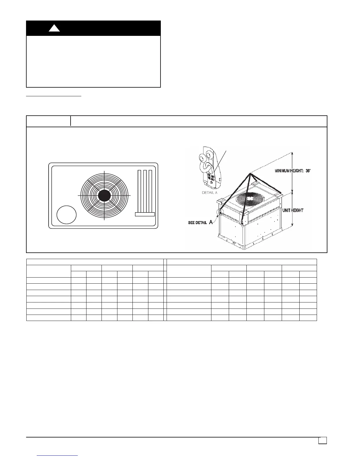
be a minimum of 36 in. (914mm) above the unit top cover .
!
WARNING
Rigging/Lifting of Unit
1. Bend top o f brackets down approximately 30 degrees
from the corner posts.
2. Attach straps of equal length to the rigging brackets at
opposite ends of the unit. Be sure straps are rated to
hold the weight of the unit (See Fig. 5).
3. Attach a clevis of sufficient strength in the middle of the
straps. Adjust the clevis location to ensure unit is lifted
level with the ground.
4. After unit is securely in p lace detach rigging straps.
Remove corner posts screws, and rigging brackets
then reinstall screws.
After the unit is placed on the roof curb or mounting pad,
remove the top crating.
FIGURE 5
Unit Corner Weight (lbs) and Rigging
x
y
1
2
3
4
Rigging Brackets are factory installed on
3---phase units only. Single---phase units
require accessory kit NPLIFTBK003A10
CORNER WEIGHTS (SMALL CABINET) CORNER WEIGHTS (LARGE CABINET)
Unit
PGN324
PGN330 PGN336
Unit
PGN342 PGN348 PGN360
lb kg
lb kg lb kg
lb kg lb kg lb kg
Total Weight 343 156
355 161 360 163
Total Weight 450 204 480 218 484 220
Corner Weight 1 69 31
75 34 74 34
Corner Weight 1 90 41 97 44 98 45
Corner Weight 2 53 24
56 25 55 25
Corner Weight 2 72 33 74 34 75 34
Corner Weight 3 83 38
81 37 86 39
Corner Weight 3 110 50 116 53 118 54
Corner Weight 4 138 63
143 65 145 66
Corner Weight 4 176 81 193 88 193 88
Rigging Weight 353 160
365 166 370 168
Rigging Weight 465 211 495 225 499 226
Shipping Weight 383 173
395 179 400 181
Shipping Weight 510 231 540 245 544 247