8. Start-up Procedures
ELECTRICAL SHOCK HAZARD.
Failure to follow this warning could result in personal
injury, and/or death.
Use extreme care during all of the following checks
and procedures.
Make sure electric power i8 turned OFF as instructed
in appropriate steps.
Circulating Air Blower
Determining Blower Speed
1.Turn electric power OFF.
2. From the system design, determine the total external static
pressure (ESP) for the supply ducts, return ducts and
registers, diffusers, grilles, dampers, heaters and filters.
3.To your system ESP determined in Step 2, add 0.05 In. W.C.
for a wet coil.
4.From the system design, determine the desired cooling
airflow in cubic feet per minute (CFM).
5.Locate the unit's Blower Performance Data table in Figure 8.
From the table, determine the speed tap required to achieve
the desired airflow.
6.See next section, Speed Taps, to set the blower motor speed
terminal block (speed taps) to the cooling speed determined
in the previous steps.
Speed Taps
After determining the required CFM and speed tap data from the
Figure 8, follow the steps below to change speeds if necessary.
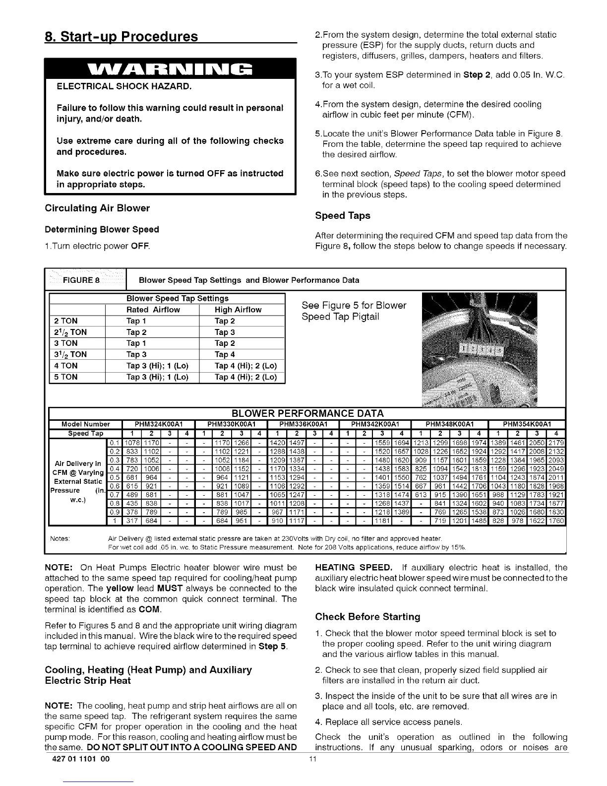
FIGURE 8 Blower Speed Tap Settings and Blower Performance Data
Blower Speed Tap Settings
Rated Airflow High Airflow
2 TON Tap 1 Tap 2
21/2 TON Tap 2 Tap 3
3 TON Tap 1 Tap 2
31/2 TON Tap 3 Tap 4
4 TON Tap 3 (Hi); 1 (Lo) Tap 4 (Hi); 2 (Lo)
5 TON Tap 3 (Hi); 1 (Lo) Tap 4 (Hi); 2 (Lo)
See Figure 5 for Blower
Speed Tap Pigtail
BLOWER PERFORMANCE DATA
Model Number PHM324K00A1 PHM330K00A1 PHM336K00A1 PHM342K00A1 PHM348K00A1 PHM354K00A1
Speed Tap 1 2 3 4 1 2 3 4 1 2 3 4 1 2 3 4 1 2 3 4 1 2 3 4
0.1 1078 1170 1170 1266 1420 1497 1559 1694 1213 1299 1698 1974 1389 1461 205C 2179
0.2 833 1102 1102 1221 1288 1433 1520 1657 1028 1226 1652 1924 1292 1417 2003 2132
Air Delivery in 0.3 783 1052 1052 1184 1209 1387 1480 1620 909 1157 1601 1859 1228 1364 1963 2093
CFM@Varying 0.4 720 1006 - 1006 1152 1170 1334 1438 1583 825 1094 1542 1813 159 1296 1923 2049
0.5 681 964 964 1121 1153 1294 1401 1550 762 1037 1494 1761 104 1243 1874 2011
External Static
0.6 615 921 921 1089 1106 1292 1359 1514 667 961 1442 1706 1043 1180 1823 1968
Pressure (in, 0.7 489 881 881 1047 1065 1247 1318 1474 613 915 1390 1651 988 1129 1783 1921
w.c.) 0.8 435 838 838 1017 1011 1203 1268 1437 841 1324 1602 940 1083 1734 1877
0.9 378 789 789 985 967 1171 1218 1389 769 1265 1538 873 1026 168C 1830
1 317 684 684 951 910 1117 1181 719 1201 1485 828 978 162,2 1760
Notes: Air Delivery @ listed external static pressre are taken at 230Volts with Dry coit, no filter and approved heater
For wet coil add .05 in. wc to Static Pressure measurement Note for 208 Votts appIications, reduce airflow by 15%
NOTE: On Heat Pumps Electric heater blower wire must be
attached to the same speed tap required for cooling/heat pump
operation. The yellow lead MUST always be connected to the
speed tap block at the common quick connect terminal. The
terminal is identified as COM.
Refer to Figures 5 and 8 and the appropriate unit wiring diagram
included in this manual. Wire the black wire to the required speed
tap terminal to achieve required airflow determined in Step 5.
HEATING SPEED, If auxiliary electric heat is installed, the
auxiliary electric heat blower speed wire must be connected to the
black wire insulated quick connect terminal.
Check Before Starting
1. Check that the blower motor speed terminal block is set to
the proper cooling speed. Refer to the unit wiring diagram
and the various airflow tables in this manual.
Cooling, Heating (Heat Pump) and Auxiliary
Electric Strip Heat
2. Check to see that clean, properly sized field supplied air
filters are installed in the return air duct.
NOTE: The cooling, heat pump and strip heat airflows are all on
the same speed tap. The refrigerant system requires the same
specific CFM for proper operation in the cooling and the heat
pump mode. For this reason, cooling and heating airflow must be
the same. DO NOT SPLIT OUT INTO A COOLING SPEED AND
427 01 1101 oo
3. Inspect the inside of the unit to be sure that all wires are in
place and all tools, etc. are removed.
4. Replace all service access panels.
Check the unit's operation as outlined in the following
instructions. If any unusual sparking, odors or noises are
11