Condensate Drain
The condensate drain outlet is a 3/4" (19.1 mm) threaded female
PVC connection located at the bottom of the unit to the left of the
evaporator access panel.
The circulating blower and the condenser fan create a negative
pressure on the condensate drain line that wil! prevent the
condensate from draining properly without a trap. To combat this
negative pressure, a field supplied condensate trap that will allow
a standing column of water of at least 2" (50.Smm) MUST be
installed. The outlet of the trap must be at least 1" below the unit
drain connection. Install the trap as near to the unit as possible
for proper drainage.
A 3/4" (19.1 mm) drain line MUST be installed if required by local
codes or if location of unit requires it. Run the drain line to an open
drain or other suitable disposal point as designated by local code.
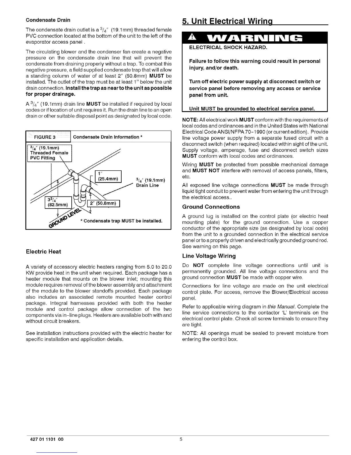
FIGURE 3 Condensate Drain Information *
3/4" (19,1mm)
Threaded Female
PVC Fitting
_4.Smm)
mm>I
3/4" (19,1mm)
Drain Line
* Condensate trap MUST be installed.
Electric Heat
A variety of accessory electric heaters ranging from 5.0 to 20.0
KW provide heat in the unit when required. Each package has a
heater module that mounts on the blower inlet; mounting this
module requires removal of the blower assembly and attachment
of the module to the blower standoffs provided. Each package
also includes an associated remote mounted heater control
package. Integral harnesses provided with both the heater
module and control package allow connection of the two
components via in-line plugs. Heaters are available both with and
without circuit breakers.
See installation instructions provided with the electric heater for
specific installation and application details.
5. Unit Electrical Wiring
ELECTRICAL SHOCK HAZARD.
Failure to follow this warning could result in personal
injury, and/or death.
Turn off electric power supply at disconnect switch or
service panel before removing any access or service
panel from unit.
Unit MUST be ,grounded to electrical service panel.
NOTE: All electrical work MUST conform with the requirements of
local codes and ordinances and in the United States with National
Electrical Code ANSI/NFPA 70-1990 (orcurrent edition). Provide
line voltage power supply from a separate fused circuit with a
disconnect switch (when required) located within sight of the unit.
Supply voltage, amperage, fuse and disconnect switch sizes
MUST conform with local codes and ordinances.
Wiring MUST be protected from possible mechanical damage
and MUST NOT interfere with removal of access panels, filters,
etc.
All exposed line voltage connections MUST be made through
liquid tight conduit to prevent water from entering the unit through
the electrical access..
Ground Connections
A ground lug is installed on the control plate (or electric heat
mounting plate) for the ground connection. Use a copper
conductor of the appropriate size (as designated by local code)
from the unit to a grounded connection in the electrical service
panel or to a properly driven and electrically grounded ground rod.
See warning on this page.
Line Voltage Wiring
Do NOT complete line voltage connections until unit is
permanently grounded. All line voltage connections and the
ground connection MUST be made with copper wire.
Connections for line voltage are made on the unit electrical
control plate. For access, remove the Blower/Electrical access
panel.
Refer to applicable wiring diagram in this Manual. Complete the
line service connections to the contactor 'L' terminals on the
electrical control plate. Check all screw terminals to ensure they
are tight.
NOTE: All openings must be sealed to prevent moisture from
entering the control box.
427 01 1101 00 5