Do NOT install the unit in a location that will permit
discharged air from the condenser to recirculate to the
condenser inlet,
UNIT DAMAGE HAZARD
Failure to follow this caution may result in shorten life
of unit components.
Do NOT operate unit in a corrosive atmosphere
containing chlorine, fluorine, or any other corrosive
chemicals.
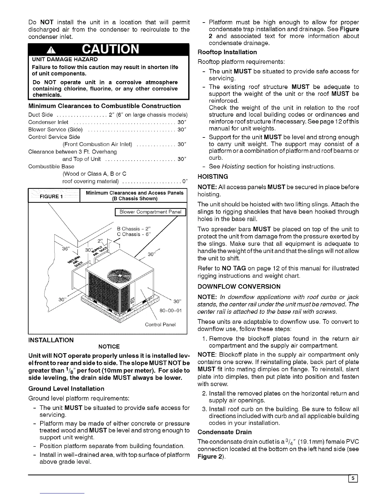
Minimum Clearances to Combustible Construction
DuctSide .................. 2" (6" on largechassis models)
Condenser Inlet .................................... 30"
BlowerService (Side) ............................... 30"
Control Service Side
(Front Combustion Air Inlet) .............. 30"
Clearance between 3 Ft. Overhang
and Top of Unit ......................... 30"
Combustible Base
(Woodor Class A, B or C
roof covering material) ..................... 0"
Minlmomc,earoooosoodAooesspano,sCho si Shownl
Biower Compartment Panel
B Chassis - 2"
C Chassis - 6"
80"
80-00-01
Control Panet
INSTALLATION
NOTICE
Unit will NOT operate properly unless it is installed lev-
el front to rear and side to side. The slope MUST NOT be
1 ,
greater than /8 perfoot (10mm per meter). For side to
side leveling, the drain side MUST always be lower.
Ground Level Installation
Ground level platform requirements:
- The unit MUST be situated to provide safe access for
servicing.
Platform may be made of either concrete or pressure
treated wood and MUST be level and strong enough to
support unit weight.
Position platform separate from building foundation.
Install in well-drained area, with top surface of platform
above grade level.
- Platform must be high enough to allow for proper
condensate trap installation and drainage. See Figure
2 and associated text for more information about
condensate drainage.
Rooftop Installation
Rooftop platform requirements:
- The unit MUST be situated to provide safe access for
servicing.
- The existing roof structure MUST be adequate to
support the weight of the unit or the roof MUST be
reinforced.
Check the weight of the unit in relation to the roof
structure and local building codes or ordinances and
reinforce roof structu re if necessary. See page 12 of this
manual for unit weights.
- Support for the unit MUST be level and strong enough
to carry unit weight. The support may consist of a
platform or a combination of platform and roof beams or
curb.
- See Hoisting section for hoisting instructions.
HOISTING
NOTE: All access panels MUST be secured in place before
hoisting.
The unit should be hoisted with two lifting slings. Attach the
slings to rigging shackles that have been hooked through
holes in the base rail.
Two spreader bars MUST be placed on top of the unit to
protect the unit from damage from the pressure exerted by
the slings, Make sure that all equipment is adequate to
handle the weight ofthe unit and that the slings will not allow
the unit to shift,
Refer to NO TAG on page 12 of this manual for illustrated
rigging instructions and weight chart,
DOWNFLOW CONVERSION
NOTE: In downflow applications with roof curbs or jack
stands, the center rail under the unit must be removed. The
center rail is attached to the base rail with screws.
These units are adaptable to downflow use, To convert to
downflow use, follow these steps:
1. Remove the blockoff plates found in the return air
compartment and the supply air compartment.
NOTE: Blockoff plate in the supply air compartment only
contains one screw. If reinstalling plate, back part of plate
MUST fit into mating dimples on flange. To reinstall, slant
plate into dimples, then put plate into position and fasten
with screw.
2. Install the removed plates on the horizontal return and
supply air openings.
3, Install roof curb on the building. Be sure to follow all
directions included with curb and all applicable building
codes in your installation.
Condensate Drain
The condensate drain outlet is a 3/4'' (19.1 mm) female PVC
connection located at the bottom on the left hand side (see
Figure 2),
151