ADS-RR(SR)-MUS01-DS-IG-EN maestro.idatalink.com
Ford Mustang Base 2010-2012
Automotive Data Solutions Inc. © 2019
3
INSTALLATION INSTRUCTIONS
STEP 1
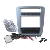
• Unbox the MUS1 dash kit and the aftermarket radio.
• Insert the storage pocket into the backside of the MUS1
radio panel and secure it with the screws included in the
dash kit. (1.1)
• Choose 3 button covers and secure them onto the button
bar (1.2 & 1.3)
• Secure the MUS1 steel radio brackets to the aftermarket
radio using the screws included with the aftermarket radio.
(1.4)
NOTE: To replace a button cover, unscrew the button bar
from the backside of the dash kit and remove the button
cover carefully.
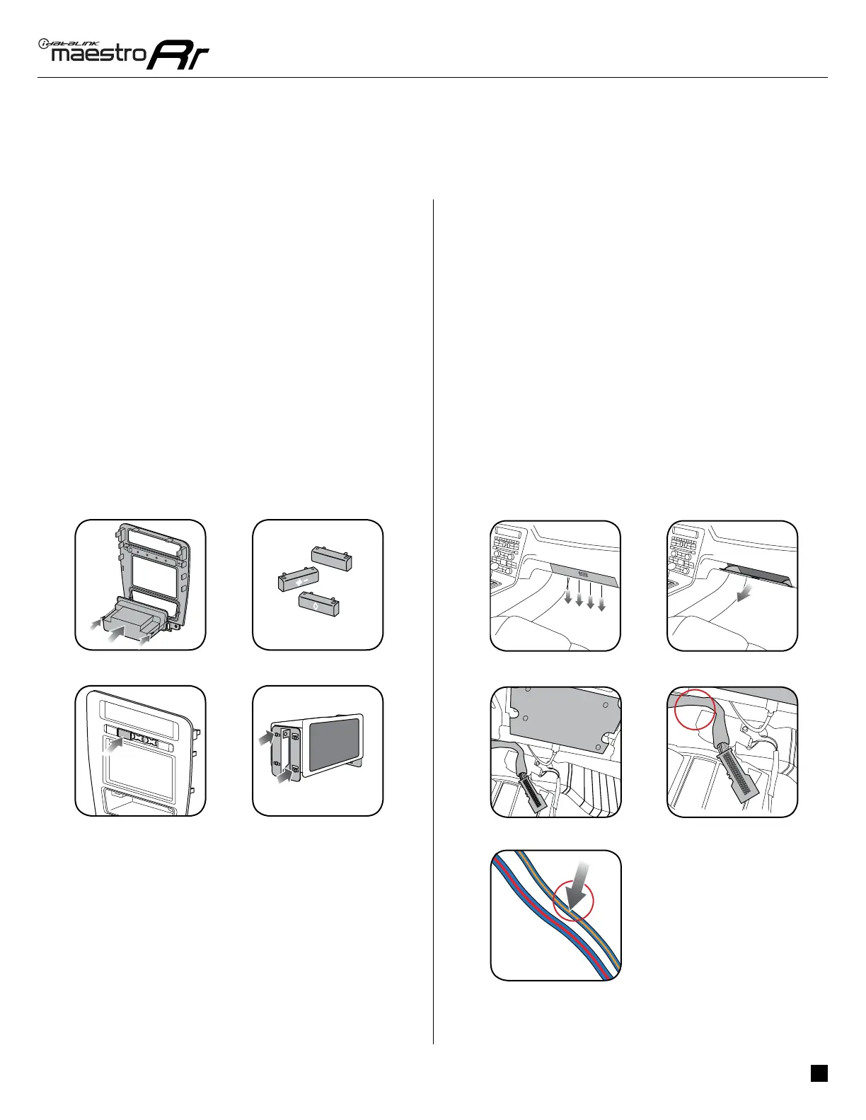
STEP 2
(with SYNC only)
• Unscrew and remove the 4 screws located underthe glove
box then open and remove the glove box carefully. (2.1 &
2.2)
• Locate the SWI 2 wire in the vehicle SYNC harness: small
gauge BLUE/ORANGE wire. Warning: a bigger gauge blue/
red wire is located in the harness.) (2.3-2.5)
• Use a multimeter to test the SWI 2 wire.
• Connect the BLACK test probe to ground (-) and connect
the RED test probe to the wire SWI 2 wire. Have the
ignition and the radio ON. If the SWI 2 wire is connected,
the multimeter will display approximately 5 volts. This
value will drop upon pressing the steering wheel voice,
phone or OK button. Once the SWI 2 wire is located and
tested, go to the next step.
A/C
Fig. 1.2
Fig. 2.2
Fig. 2.4
4
 Loading...