Page 6
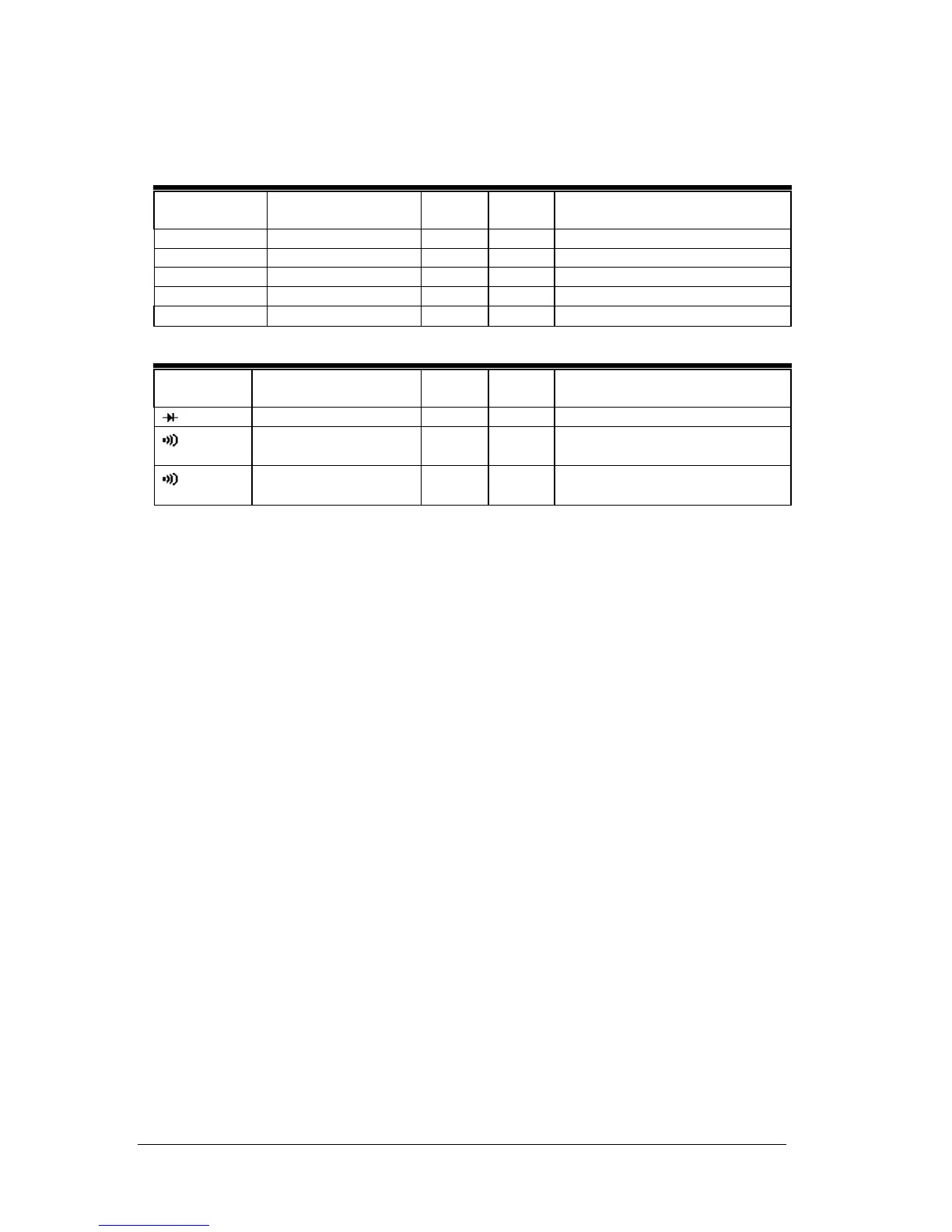
Table 4 Capacitance, Frequency, and Resistance Test
Function
/Range
Input
Low
Limit
High
Limit
Model number
Hz {auto} 1KHz @ 10V .996 1.004 61-700, 61-701
Hz {auto} 10KHz @ 10V 9.96 10.04 61-700, 61-701
MFD 200 100µF 96.5 103.5 61-701, 61-702, 61-704
Ω 200 100Ω
98.7 101.3 61-700, 61-701, 61-702, 61-704
Ω 200K 100KΩ
98.7 101.3 61-700, 61-701, 61-702, 61-704
Table 5 Diode and Continuity Check
Function
/Range
Test Value
Low
limits
High
Limit
Model number
Diode 500mV DC 485 515 61-700, 61-701, 61-702, 61-704
Continuity
40Ω beep on,
150Ω beep off
61-700, 61-701
Continuity
50Ω beep on,
300Ω beep off
61-702, 61-704
CALIBRATION
Calibration Preparation
1. Turn on the calibrator, allow calibrator to warm up. Perform calibration at
23±2°C at relative humidity of < 70%. Temperature stabilization should be
reached after 30 minutes.
2. Disconnect the test leads and turn the range switch to “OFF”.
3. Remove the screws holding the battery cover and one at the jaw.
4. Remove the case bottom using care not to damage the battery connector and leads
to the continuity beeper. (Beeper is attached to the bottom case cover.)
5. Using a calibrated meter ensure the battery measures a minimum of 7.5V DC.
If the battery measures under 7.5V DC, replace the battery.
Calibration Procedure
It is recommended that all IDEAL meters undergo the following calibration procedure on
an annual basis.
The class of calibrator or equipment should have an accuracy that exceeds, by an expectable ratio the
accuracy of this instrument.
Form number TM61700-1-2-4 Rev 4 September 2004