1
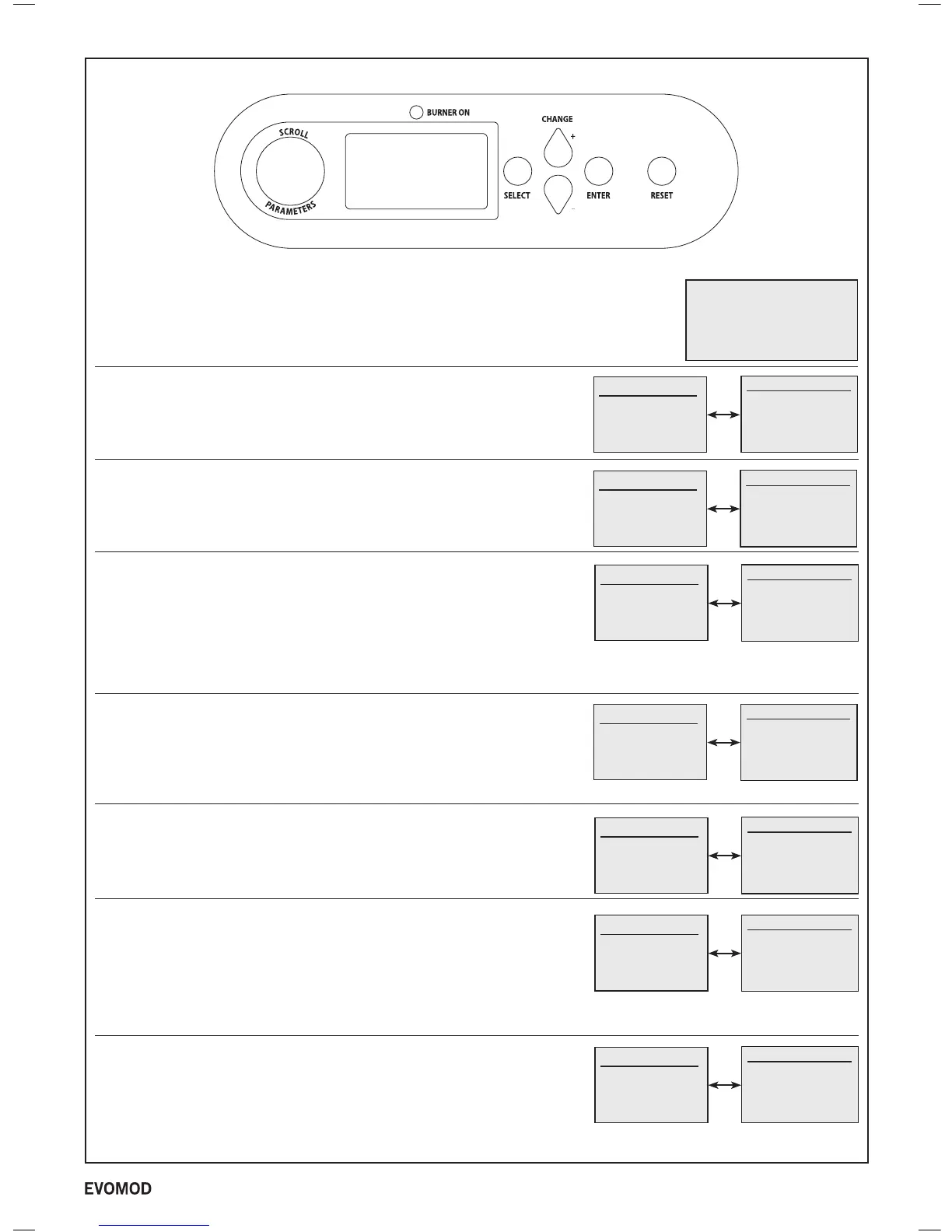
BOILER CONTROLS / DISPLAY (MASTER PANEL SHOWN)
3
Initialising Please Wait
U/I PCB 330.E18
Pri’ PCB 332.E08
Off Mode
Module 1 Standby
Module 2 Standby
Module 3 Standby
Module 4 Standby
Ideal
Mains On
When the mains to the boiler is switched on a screen similar to the following will be displayed.
Off Mode
If the boiler has been switched to Off Mode the following screens will be diusplayed.
No Boiler operation will take place with this setting. See page 26 to change to On Mode.
For a 250kW boiler only Module1 will be shown, for a 500kW boiler only Module1
and Module2 will be shown etc.
Heat Demand Off, Switched Live Mode
If there is no Heat Demand from the External Switched Live Control then screens similar to the
following will be displayed. See page 28 to set the boiler for 0-10V Operation.
For a 250kW boiler only Module1 will be shown, for a 500kW boiler only Module1 and Module2
will be shown etc.
Heat Demand On, Switched Live Mode
If there is an ongoing Heat Demand generated by the switched live to the boiler being on then
screens similar to the following will be displayed.
The Flow Setpoint will vary depending on its setting. See page 26 for adjusting Flow Setpoint.
Flow Temp will vary with the actual ow temperature of the boiler.
Either Standby, Fan Pre-Purge, Ignition, Burner On, Fan Post-Purge or Pump Overrun will be
shown for each module dependent on its current operating state.
For a 250kW boiler only Module1 will be shown, for a 500kW boiler only Module1 and Module2
will be shown etc.
Boiler Frost Protection Mode
If the boiler ow temperature drops below 5°C screens similar to the following will be displayed.
Flow Temp will vary with the actual ow temperature of the boiler.
Either Standby, Fan Pre-Purge, Ignition, Burner On, Fan Post-Purge or Pump Overrun will be
shown for each module independently dependent on its current operating state.
For a 250kW boiler only Module1 will be shown, for a 500kW boiler only Module1 and Module2
will be shown etc.
Heat Demand Off, 0-10V Operating Mode
If there is no Heat Demand from the External 0-10V Control then a screen similar to the following
will be displayed. See page 28 to set the boiler to Switched Live Operation.
For a 250kW boiler only Module1 will be shown, for a 500kW boiler only Module1 and Module2
will be shown etc.
Heat Demand On, 0-10V Capacity Operating Mode
If there is an ongoing Heat Demand generated by the 0-10V signal to the boiler, and the boiler is
congured for 0-10V Capacity Operation, then screens similar to the following will be displayed.
See page 28 to set the boiler to 0-10V Temperature Operation.
The Target Output will vary dependent on the 0-10V signal.
Actual Output will vary with actual burner outputs of the boiler.
Flow Temp will vary with the actual ow temperature of the boiler.
Either Standby, Fan Pre-Purge, Ignition, Burner On, Fan Post-Purge or Pump Overrun will be
shown for each module dependent on its current operating state.
Heat Demand On, 0-10V Temperature Operating Mode
If there is an ongoing Heat Demand generated by the 0-10V signal to the boiler, and the boiler is
congured for 0-10V Temperature Operation, then screens similar to the following will be displayed.
See page 28 to set the boiler to 0-10V Capacity Operation.
The Flow Setpoint will vary dependent on the 0-10V signal.
Flow Temp will vary with the actual ow temperature of the boiler
Either Standby, Fan Pre-Purge, Ignition, Burner On, Fan Post-Purge or Pump Overrun will be
shown for each module dependent on its current operating state.
Off Mode
For Heating
select On Mode
Press select for Menu
EVOMOD USER INTERFACE
Heat Demand Off
Module 1 Standby
Module 2 Standby
Module 3 Standby
Module 4 Standby
Heat Demand Off
No Heat Demand
from Switched Live
Press select for Menu
Heat Demand On
Module 1 Burner On
Module 2 Burner On
Module 3 Standby
Module 4 Standby
Heat Demand On
Switched Live On
Flow Setpoint 80˚C
Flow Temp 80˚C
Press select for Menu
Heat Deman On
Mod 1 Burner on
Mod 2 Burner On
Mod 3 Standby
Mod 4 Standby
Heat Demand On
Boiler Frost Protection
Frost Setpoint 5˚C
Flow Temp 5˚C
Press select for Menu
Heat Demand Off
Module 1 Standby
Module 2 Standby
Module 3 Standby
Module 4 Standby
Heat Demand Off
No Heat Demand
from 0-10V Input
Press select for Menu
Heat Demand On
Module 1 Burner On
Module 2 Burner On
Module 3 Standby
Module 4 Standby
Heat Demand On
0-10V Input = 10V
Target Output = 100%
Actual Output = 100%
Flow Temp 20˚C
Heat Demand On
Module 1 Burner On
Module 2 Burner On
Module 3 Standby
Module 4 Standby
Heat Demand On
0-10V Input = 10V
Flow Setpoint 80˚C
Flow Temp 80˚C
Press select for Menu
- Users
 Loading...


